Installation guide, Operation, Product diagram – Veris Industries H8126-CB Install User Manual
Page 2
VERIS INDUSTRIES
™
H8126-CB
INSTALLATION GUIDE
Z203167-0A
PAGE 2
©2009 Veris Industries USA 800.354.8556 or +1(0)503.598.4564 / [email protected]
10092
Alta Labs, Enercept, Enspector, Hawkeye, Trustat, Veris, and the Veris ‘V’ logo are trademarks or registered trademarks of Veris Industries, L.L.C. in the USA and/or other countries.
oPeratIon
The H8126-CB Energy Meter Communication Board is an optional field-installable
board for the H8163 Energy Meter, providing N2 communications capability. The
H8126-CB also enables the energy meter to provide true kW & kVAR demand
information.
The easy-to-install H8126-CB provides a simple, cost-effective way to network the
H8163 Energy Meter on the N2 bus.
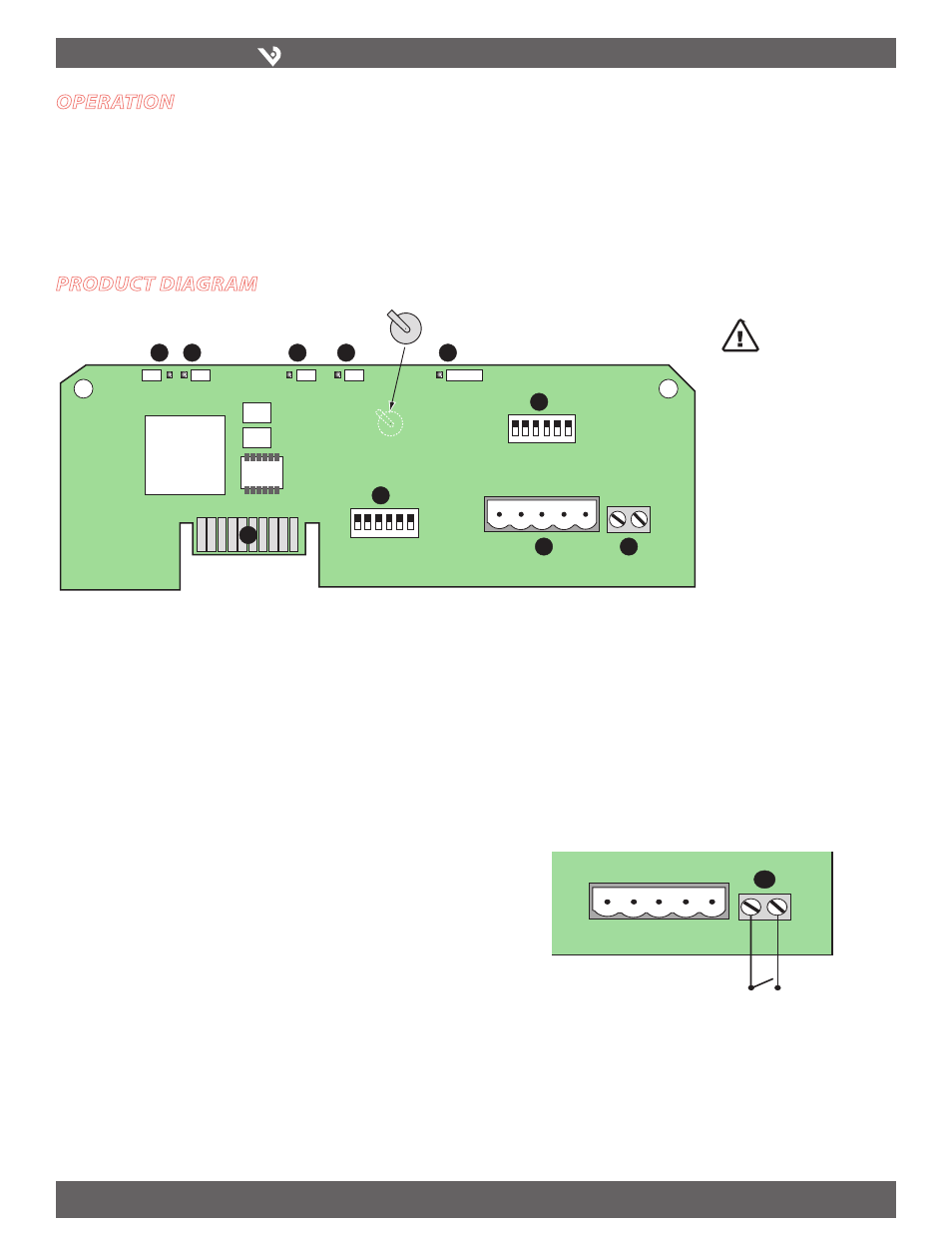
Product dIagram
ON
1 2 3 4 5 6
ON
1 2 3 4 5 6
1
2
TX
RX
3
RX
4
TX
5
6
7
8
9
10
ALIVE
LITHIUM BATTERY
10
RS-485 LED (TX):
1.
Red LED; blinks to indicate that the H8126-CB is transmitting
data to the master.
RS-485 LED (RX):
2.
Red LED; blinks to indicate that the H8126-CB is receiving data
from the master.
LED from Main Board (RX):
3.
Green LED; blinks to indicate that the H8126-CB is
receiving data from the main board.
LED from Main Board (TX):
4.
Green LED; blinks to indicate that the H8126-CB is
transmitting data to the main board.
“ALIVE” LED:
5.
Green LED; should blink once per second to indicate normal
operation of the H8126-CB.
N2 Network Address DIP Switches:
6.
Use these DIP switches to set the network
address for the H8126-CB. See the Settings table on page 3 for more information.
7.
Connection to Energy Meter:
Install the H8126-CB in the energy meter by
inserting this connector into the connection slot at the top of the energy meter.
Communication DIP Switches:
8.
N2 factory default
RS-485 Communication Terminals:
9.
Insert the RS-485 connector into these
terminals. See Wiring Diagrams on page 4 for instructions on wiring the connector
for 2-wire or 4-wire communications.
End of Demand Subinterval Terminal:
10.
Use this terminal as the input
connector for “end of demand interval” signal from the utility or other source. An
interposing isolated relay should be used as the dry contact for this
terminal, as pictured below. Do not apply voltage to this connection.
CAUTION! Danger of
explosion if battery is
incorrectly replaced.
Replace only with the
same or equivalent type
recommended by the
manufacturer. Dispose of
used batteries according
to the manufacturer’s
instructions.