Wheel and wheel valve, Drive axle wheel end service – Spicer TPCS (Tire Pressure Control System) Service Manual User Manual
Page 48
48
Wheel and Wheel Valve
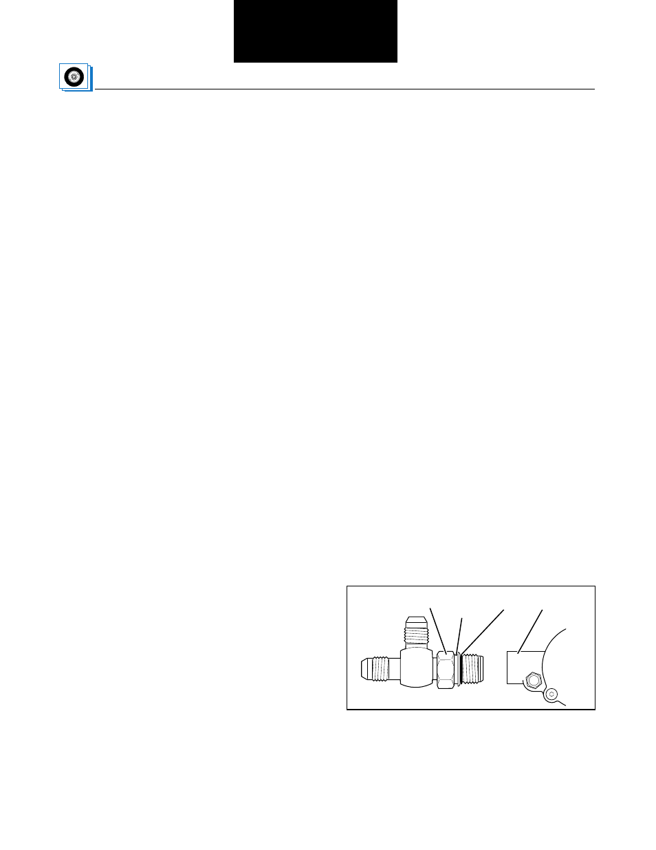
Figure 37 is a detailed view of the external air line
connections on a rear drive wheel.
Note: Perform the following steps with the wheels off
the ground to prevent the tires from losing bead seal.
Install drive axle wheel end pneumatics as follows:
1. Mount inside and outside drive wheels so that both
valve stems are positioned together and 180° from
the axle hub air fitting. Feed inner tire hose out
through wheel edge opening. Position hoses so
they will connect easily to wheel valve as shown in
Figure 38. Double check hose alignment.
2. Select two hub mounting studs that will position
wheel valve outlet port 180° from the axle hub air
fitting as shown in Figure 37. Remove the nuts
and lockwashers on the selected hub studs. Install
the wheel valve mounting bracket and replace the
hub lockwashers and nuts.
3. Set wheel valve within mounting bracket and fasten
to the wheel valve mounting bracket using
3
/
8
" x 1"
hex head bolts.
Note: Replace the air filter in wheel valve when the tire
or wheel valve is serviced. See Figure 37.
4. Prepare the wheel valve and hoses in the following
manner to minimize air loss from the tire when
reinstalling tire hoses.
A. Lubricate O-ring.
B. Secure lock nut against the O-ring washer.
C. Install the tee into the valve until the O-ring is
seated and the washer is against the face of the
valve.
D. Back off lock nut.
E. Turn tee clockwise to orient fitting – no more than
one turn.
F. Tighten lock nut 16–19 lbs. ft. (22–26 N•m).
Note: Work quickly to minimize air loss during
steps 5-8.
5. Remove valve stem core from inner tire, install hose
end on valve stem.
6. Remove valve stem core from outer tire, install hose
end on valve stem.
7. Install outer hose on run tee. Torque to 16–19 lbs. ft.
(22–26 N•m)
8. Install inner hose on branch tee. Torque to
16–19 lbs. ft. (22–26 N•m)
Figure 37 Run Tee
Locknut
O-ring
Washer
O-ring
Valve