Wiring connections, Electrical service, Wiring connections configuration connector – Spicer TPCS (Tire Pressure Control System) Service Manual User Manual
Page 16: Relay and power connections, Vehicle grounds, Lamp switch
16
Wiring Connections
Configuration Connector
This connector initializes the Electronic Control Unit for
the current vehicle configuration (see Figure 9). De-
pending on application, factory supplied jumper con-
nector may be provided.
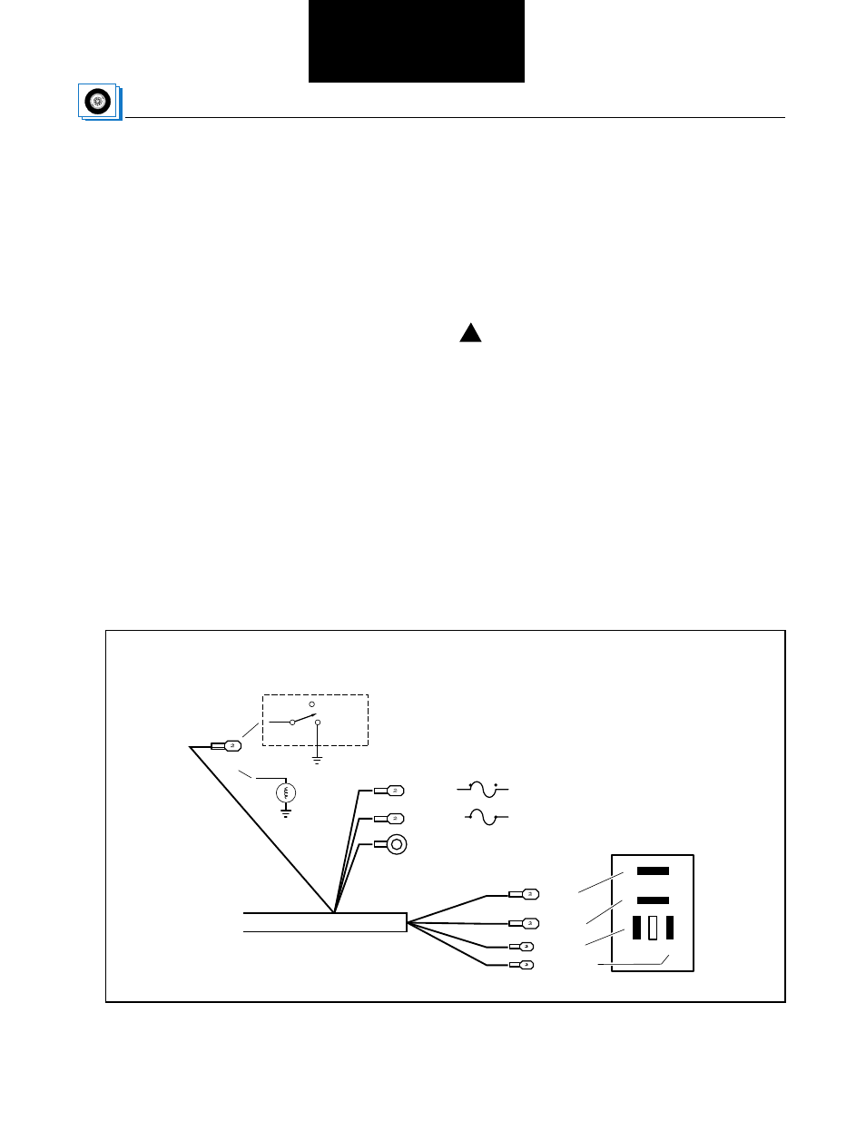
Relay and Power Connections
Figure 7 shows the terminal connections to the relay
and the vehicle power panel. The connections must be
made as shown. The relay lugs plug into the bottom of
the relay sockets.
Vehicle Grounds
There are three ground terminals that must be secured
to the vehicle chassis. The ground terminals are for the
Electronic Control Unit, Operator Control Panel and
vehicle interface. Figure 3 shows the three grounds and
their attachment points.
Caution: The battery and the switched ignition are
fused individually with a circuit breaker or a fuse.
(See Figure 7 for power requirements.)
Lamp Switch
The lamp wire provides back-lighting for the Operator
Control Panel keypad and dims the display. Some
vehicles use a separate switch to control intensity. This
may be connected to the headlamp circuit, a day time
running light (DRL) system or a separate switch. This
is a switched input and cannot be connected directly to
the dimmer switch.
!
Figure 7 Terminal Connections
RSP 3
VBATT 2
VBATT 1
RLY1ENA
Relay Lugs
Vehicle Power Panel
VBATT
SWACC 3
1
4
2
5
3
Relay
Top View (relay side)
To battery
20 amp fuse
To ignition switch
5 amp fuse
GND 8
(vehicle ground)
LAMP 2
Lamp Switch
Normal
(Bright)
Dim
To
headlamp
or
No Connection