Pneumatic control unit replacement, Pneumatic service – Spicer TPCS (Tire Pressure Control System) Service Manual User Manual
Page 21
21
!
Pneumatic Control Unit
Replacement
4. Note the Pneumatic air line location, mark if
necessary.
5. Remove the pneumatic connections from the
Pneumatic Control Unit.
6. Remove the Pneumatic Control Unit.
7. Mount the new Pneumatic Control Unit.
Note: Apply light coating of removable thread sealing
compound to the NPT fittings before installing.
8. Install
1
/
4
" male NPT to
1
/
2
" nylon air brake tubing
fitting into Supply, Trailer, and Drive ports the
Pneumatic Control Unit.
9. Install
1
/
4
" male NPT to
3
/
8
" NPT female increasing
adapter to
3
/
8
" male NPT to
5
/
8
" nylon air brake
tubing fitting into the steer port of the Pneumatic
Control Unit.
10. Attach the Pneumatic air line to the Pneumatic
Control Unit in the same locations as marked in
Step 4.
Pneumatic Control Unit Replacement
Note: Refer to Figure 10 for the following steps.
1. Turn off the vehicle’s ignition and engine.
Warning: Drain off air from the wet tank before
removing any fittings!
2. Locate the Pneumatic Control Unit.
3. Disconnect the wire harness connectors from the
Pneumatic Control Unit.
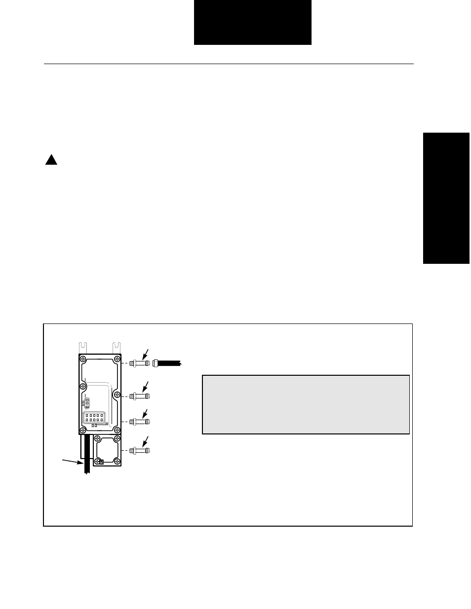
Figure 10 Pneumatic Control Unit and Pneumatic Layout
Steer
Trailer
(if equipped)
From
Wet
Tank
Drive
1
Top
View
Pneumatic
Control Unit
D O T
2
2
2
3
Vent
Hose
1. Pneumatic Control Unit vent hose
5
/
8
ID vent (heater) hose
2.
1
/
4
" male NPT to
1
/
2
" nylon air brake tubing fitting
3.
1
/
4
" male NPT to
3
/
8
" NPT female increasing adapter to
3
/
8
"
male NPT to
5
/
8
" nylon air brake tubing fitting
Note: Area highlighted shows typical connections. Actual fittings may vary by vehicle manufacturer.