Pneumatic service – Spicer TPCS (Tire Pressure Control System) Service Manual User Manual
Page 27
27
Drive Axle
Pneumatic Replacement
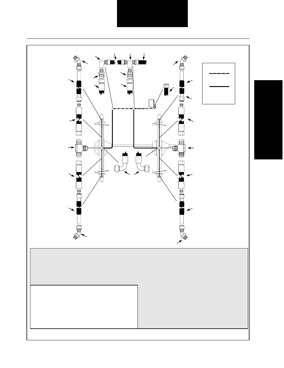
Figure 14 Drive Axle Air Line Routing
6.
5
/
16
" wire braid hose with a
3
/
8
" female 37° flare
hose end, swivel straight and a
3
/
8
" male 37° flare
hose end, straight, long arm drive axle side
7.
3
/
8
" male 37° flare union tee,
5
/
8
" diameter and
7
/
16
"
diameter mounting holes
8.
5
/
16
" wire braid hose with a
3
/
8
" female 37° flare
hose end, swivel straight, and a
3
/
8
" male 37°
flare hose end, straight, short arm drive axle side
9.
1
/
2
" nylon air brake tubing
10.
5
/
16
" wire braid hose with a
3
/
8
" female 37° flare
hose end, swivel straight, and a
3
/
8
" female 37°
flare hose end, swivel 90° elbow
1.
1
/
2
" nylon air brake tubing branch tee,
3
/
8
" NPT
female on the branch
2.
3
/
8
" male NPT to
3
/
8
" male 37° flared
3.
1
/
2
" nylon air brake tubing to
3
/
8
" female NPT, 90°
elbow
4. For 8.25" brake flange bolt circle, use
1
/
4
" male NPT
to
3
/
8
" flareless tube end, 45° elbow and
3
/
8
" NPT
1
/
4
"
female NPT reducing adaptor
4a. For 7.25" brake flange bolt circle, use
3
/
8
" male NPT
to
3
/
8
" flareless tube end and 45° elbow (not shown)
5. Drive axle inlet tube, stainless steel
Note: Area highlighted shows typical connections. Actual fittings may vary by vehicle manufacturer.
D O T
9
8
6
6
8
7
7
10
5
KEY
Plastic Tubing
See Chart in Figure 9
Wire Braid Hose
See Chart in Figure 9
PCU
D O T
D O T
9
1
9
10
D O T
3
2
10
2
5
5
5
5
4
4
4
4
A to B = A to C
A
B
C