Rotary joint, nested hubcap installation, Wheel and wheel valve, Non-drive axle wheel end service – Spicer TPCS (Tire Pressure Control System) Service Manual User Manual
Page 37
37
!
Caution: Failure to align banjo fitting at 30° may
result in the hose rubbing against hubcap.
4. Align notch in rotary valve with locating tab inside
hubcap.
5. Align hubcap gasket(s) and spacer if used. Install
6 cap screws and torque to 15 lbs. ft. (20 N•m)
using X pattern. Do not use an air gun or over-
tighten.
6. Place vent plug into center of window and snap in
position.
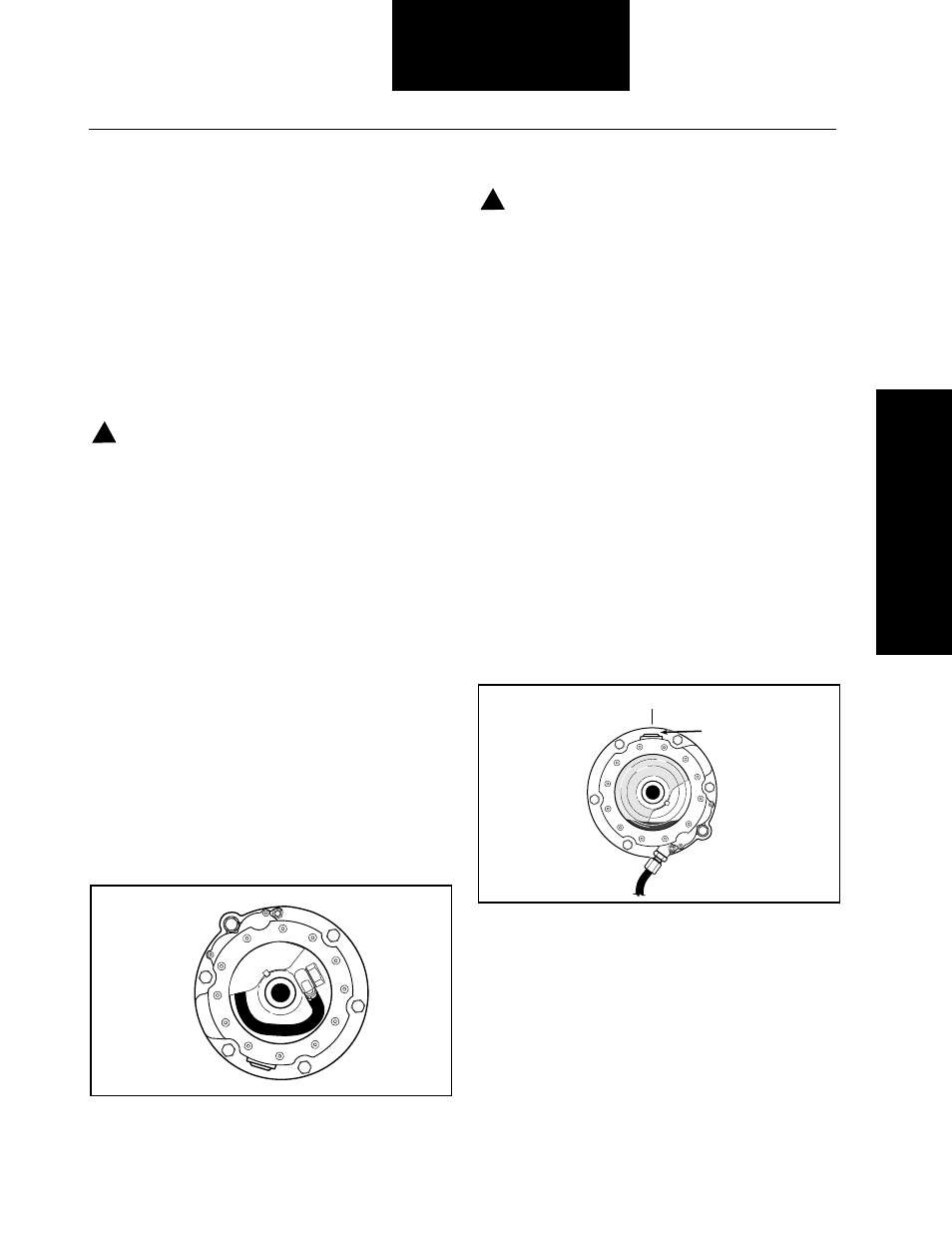
7. Fill hubcap to proper level (between add and full)
with wheel bearing lube (see Figure 23) as follows:
A. Rotate hubcap until lube fill plug is on top
(12 o’clock position).
B. Remove fill plug and add bearing lube.
C. Install fill plug and rotate wheel.
D. Recheck the bearing lube fluid level with fill
plug on top (12 o’clock position).
E. Repeat the above steps until the proper fluid
level is indicated.
Installation Procedures
Rotary Joint, Nested Hubcap Installation
To insure an airtight and watertight seal, use care when
assembling the following components. Refer to Figures
19 and 20.
1. Apply a thin coat of silicone grease to O-ring and
then apply removable thread locking compound on
threads and thread rotary joint into spindle. Torque
to 31 lbs. ft. (42 N•m), see Figure 20 (use
11
/
16
open
end wrench no more than
3
/
16
thick).
Caution: Failure to use a
11
/
16
open end wrench no
more than
3
/
16
inch thick may result in insufficient
installation torque and the possibility of the rotary
joint unscrewing in service.
Tip: Use one or two studs (or threaded rods) in the
hubcap retaining bolt holes to keep the gaskets and
spacer in place. This will aid with the installation.
2. Position gasket, spacer (if used) and the second
gasket (if used) between the hubcap and the hub.
3. Connect hose assembly to the spindle mounted
rotary seal as follows:
• Place banjo washer on banjo bolt, insert banjo
bolt into banjo fitting, place second banjo washer
on banjo bolt.
• Connect assembly the rotary joint. Position
banjo at 30° toward hub while tightening to
140-160 lbs. in. (15.8-18.1 N•m). Refer to
Figure 22.
Figure 22 Proper Hose Position
!
12 O'Clock
Fill Plug
Figure 23 Add Lube Position and Check
Wheel and Wheel Valve
Note: Figure 19 shows front steer wheel air line
connections for steer wheel applications. Use the
illustration as a reference in completing the non-drive
axle installation.
Note: Perform the following steps with the wheels off
the ground to prevent the tires from losing bead seal.