Dimensions, Example application for ec-30/fd – M&C TechGroup EC-30 Data sheet User Manual
Page 2
M&C TechGroup Germany GmbH • Rehhecke 79 • 40885 Ratingen • Germany
[email protected] • www.mc-techgroup.com • Fon +49 2102 935-0 • Fax +49 2102 935-111
6.7
Technical specifications and illustrations are without
obligation, subject to modifications. 09.96/06.06
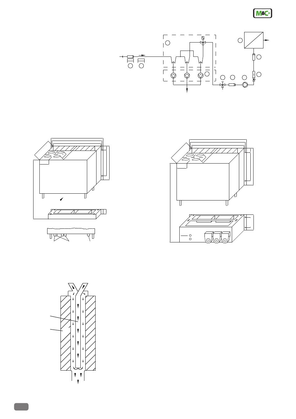
Dimensions
Dimensions in mm
Functioning diagram of M&C heat-exchanger
EC-30 basic version with unit EC-F
EC-30 basic version with unit EC-FD
355
DN 4/6
GL25/12
PG 13,5
Sample gas out
3x Condensate Out
2x cable gland
EC-30 with unit EC-F
Standard unit EC-F
45(1U)
view A
A
37,5
310 (7U)
235
240
85
70
2
1
3
360
435
465
483 (84HP)
443
37,5
310 (7U)
235
240
85
70
2
1
3
360
435
465
483 (84HP)
57
Option: unit EC-FD
SR 25
SR 25
Sample gas out
Condensate out
Universal unit
EC-FD
SR 25
133 (3U)
M&C Jet-Stream
heat exchanger
Cooling block
Condensate - OUT
Sample gas - IN
Sample gas - OUT
+2°C
-30°C
Example application for EC-30/FD
1 Heated filter sample probe SP2000-H
2 Heated sample line 4M4/6
3 Ultra low cooler EC-30
4 Universal unit EC-FD with 3 peristaltic pumps SR25.1
5 3-way ball valves 3L/PV-1
6 Fine filter FP-2T-D with liquid alarm LA1
7 Diaphragm pump MP47
8 Flow meter FM10, 25-250Nl/hr
9 Aerosol filter CLF-5/W optional according to application
10 Analyser, f.e. PMA100
-30 °C
-30 °C
+2 °C
2
1
3
EC-FD
4
Condensate OUT
5
3
10
9
8
7
EC-30
1
2
Sample gas IN
IN
Test gas
6