M-AUDIO MIDISPORT 8x8/s User Manual
Page 4
MIDISPORT outputs in the event of a stuck note or other confusion from too
much MIDI information.
4 MIDI In Indicator LEDs 1 through 8 - These LEDs will light to indicate
activity on each MIDI Input port, in response to MIDI data received from
external devices.
5. MIDI Out Indicator LEDs 1 through 8 - These LEDs will light to indicate
activity on each MIDI Out port, in response to MIDI data being sent from the
computer.
6. Write button - Starts and stops the SMPTE writer, and can also be used to set
the Write Offset time.
7. "Writing" and "Locked" LEDs - the "Writing" LED indicates SMPTE writer
status, lighting when SMPTE Write mode is engaged; The "Locked" LED
indicates SMPTE reader/regenerator status, lighting when a valid SMPTE
code is recognized at the SMPTE In jack.
8. Format button - Manually selects the format of SMPTE Output. Push
repeatedly until the proper format is set.
9. SMPTE Format LEDs - Indicates the current SMPTE output format. "24"
indicates 24 fps (frames per second), "25" indicates 25 fps, "29.97" indicates
29.97 fps, "30D" indicates 30 fps drop-frame, and "30" indicates 30 fps.
10. Mode button - Manually selects the mode in which the MIDISPORT will
operate. Push repeatedly until the proper mode is selected.
11. Mode indicator LEDs - When lit, these LEDs indicate which mode is
currently selected.
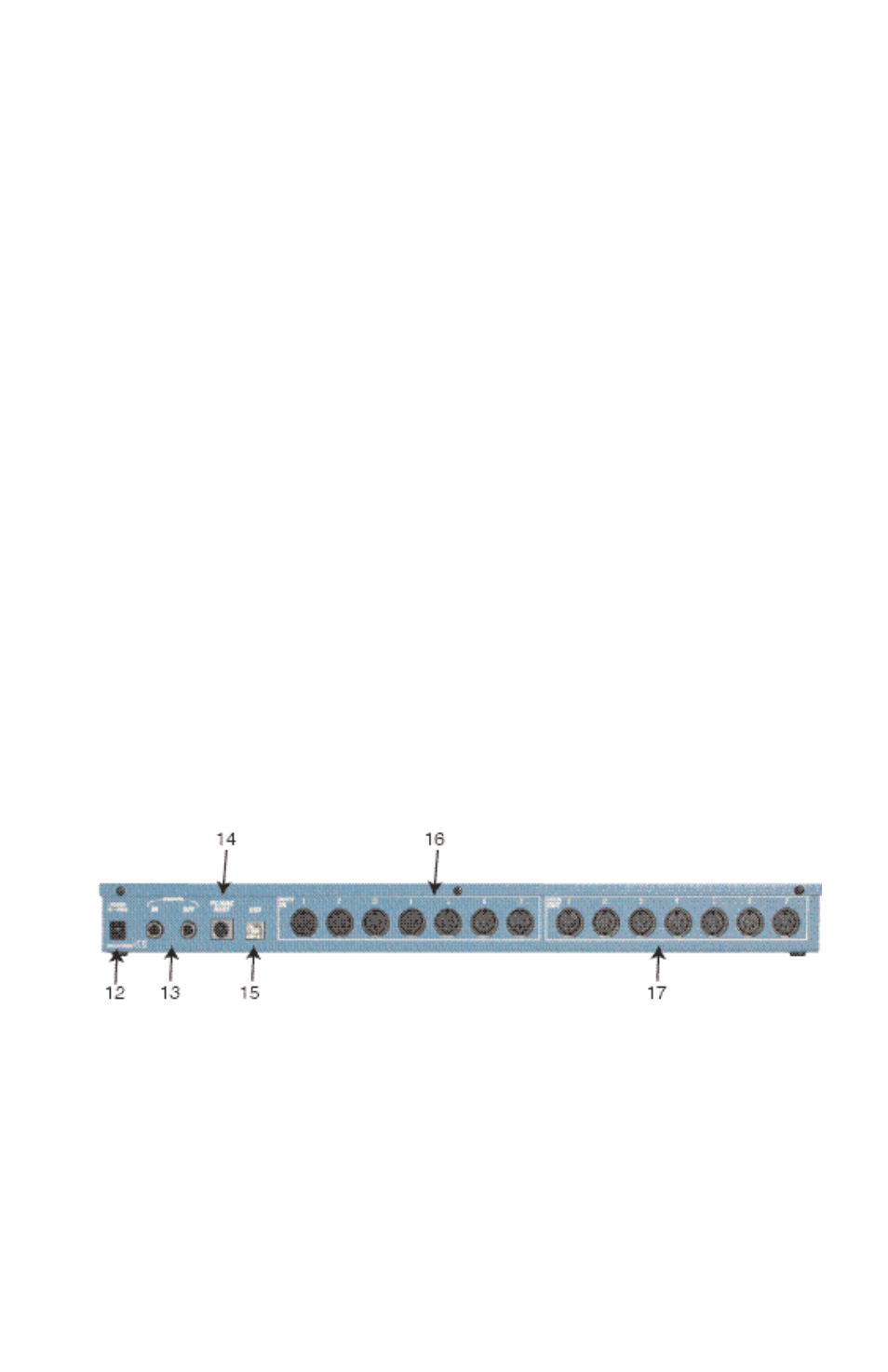
Back Panel
12. Power Jack - this 2.5 mm jack is used to connect the MIDISPORT to the “wall
wart” 9vDC power supply included with the unit. Only the proper value
power supply should be used with the MIDISPORT.
13. SMPTE In and Out Jacks - these 1/4” phone jacks receive or send a SMPTE
timecode signal, respectively.
14. PC / Mac Host Connector - this 8 pin mini-DIN connector is used to connect
the MIDISPORT to the host computer’s serial port, should the user choose to
operate in this mode.
4