Vertical speed indicator (vsi), Vertical deviation, Flight instruments – Garmin G1000 Quest Kodiak User Manual
Page 69
190-00590-03 Rev. A
Garmin G1000 Pilot’s Guide for the Quest KODIAK 100
57
FLIGHT INSTRUMENTS
SY
STEM
O
VER
VIEW
FLIGHT
INSTRUMENTS
EIS
AUDIO P
ANEL
& CNS
FLIGHT
MANA
GEMENT
HAZARD
AV
OID
ANCE
AFCS
ADDITIONAL
FEA
TURES
APPENDICES
INDEX
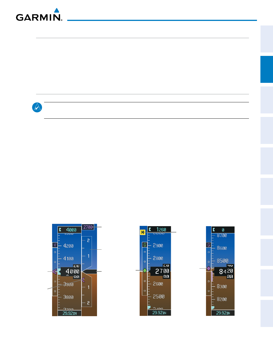
VERTICAL SPEED INDICATOR (VSI)
The Vertical Speed Indicator (VSI; Figure 2-11) displays the aircraft vertical speed on a fixed scale with labels
at 1000 and 2000 fpm and minor tick marks every 500 fpm. Digits appear in the pointer when the climb or
descent rate is greater than 100 fpm. If the rate of ascent/descent exceeds 2000 fpm, the pointer appears at the
edge of the tape and the rate appears inside the pointer.
A magenta chevron is displayed on the VSI to indicate the Required Vertical Speed for reaching a VNV target
altitude once the “TOD [Top of Descent] within 1 minute” alert has generated.
VERTICAL DEVIATION
NOTE:
The Glidepath Indicator is only shown for aircraft with GIA 63W Integrated Avionics Units when
WAAS is available.
The Vertical Deviation Indicator (VDI; Figure 2-11) is a magenta chevron indicating the baro-VNV vertical
deviation when Vertical Navigation (VNV) is being used. The VDI appears in conjunction with the “TOD within
1 minute” alert. The VDI is removed from the display if vertical deviation becomes invalid. See the Flight
Management Section for details on VNV features, and refer to Section 2.2, Supplemental Flight Data, for more
information about VNV indications on the PFD.
The Glideslope Indicator (Figure 2-12) appears to the left of the Altimeter whenever an ILS frequency is
tuned in the active NAV field. A green diamond acts as the Glideslope Indicator, like a glideslope needle on
a conventional indicator. If a localizer frequency is tuned and there is no glideslope, “NO GS” is displayed in
place of the diamond.
The glidepath is analogous to the glideslope for GPS approaches supporting WAAS vertical guidance (LNAV+V,
L/VNAV, LPV). When an approach of this type is loaded into the flight plan and GPS is the selected navigation
source, the Glidepath Indicator (Figure 2-13) appears as a magenta diamond during the approach. If the
approach type downgrades past the final approach fix (FAF), “NO GP” is displayed in place of the diamond.
Full-scale deflection of two dots is 1000 feet.
Figure 2-11 Vertical Speed and
Deviation Indicator (VSI and VDI)
Vertical
Speed
Indicator
Required
Vertical
Speed
Vertical
Speed
Pointer
VNV Target
Altitude
Vertical
Deviation
Indicator
Glipepath
Indicator
Figure 2-13 Glidepath Indicator
Glideslope
Indicator
Marker
Beacon
Annunciation
Figure 2-12 Glideslope Indicator