70 others, Monitor out computer in 1, Computer in 2 – Toshiba TLP780U User Manual
Page 70
70
Others
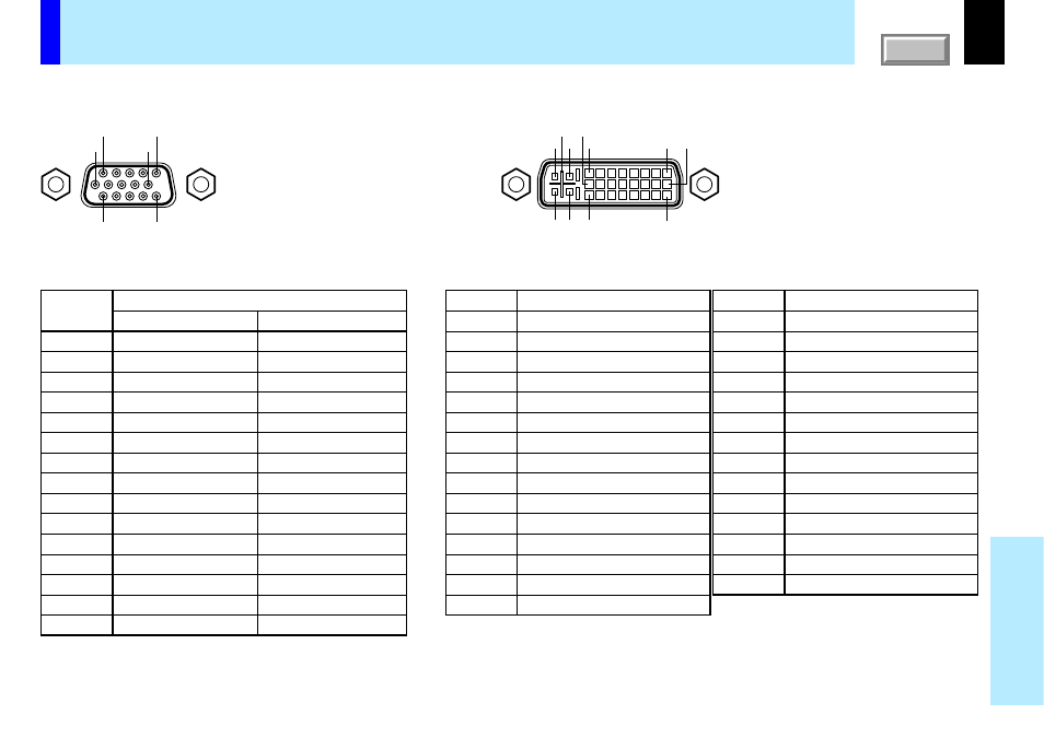
Pin No.
1
2
3
4
5
6
7
8
9
10
11
12
13
14
15
Description
RGB input
Y/P
B
/P
R
input
Video signal (Red)
Color difference signal (P
R
)
Video signal (Green)
Luminance signal (Y)
Video signal (Blue)
Color difference signal (P
B
)
GND
*
GND
*
GND (Red)
GND (P
R
)
GND (Green)
GND (Y)
GND (Blue)
GND (P
B
)
N.C
*
GND
*
GND
*
DDC data
*
Horizontal sync signal
*
Vertical sync signal
*
DDC clock
*
Pin No.
1
2
3
4
5
6
7
8
9
10
11
12
13
14
15
Description
T.M.D.S. data 2 -
T.M.D.S. data 2 +
T.M.D.S. data 2/4 shield
T.M.D.S. data 4 -
T.M.D.S. data 4 +
DDC clock
DDC data
Analog vertical sync signal
T.M.D.S. data 1 -
T.M.D.S. data 1 +
T.M.D.S. data 1/3 shield
T.M.D.S. data 3 -
T.M.D.S. data 3 +
+5V power
GND (+5V, H Sync & V Sync)
Description
Hot plug detection
T.M.D.S. data 0 -
T.M.D.S. data 0 +
T.M.D.S. data 0/5 shield
T.M.D.S. data 5 -
T.M.D.S. data 5 +
T.M.D.S. clock shield
T.M.D.S. clock +
T.M.D.S. clock -
Analog Video signal (Red)
Analog Video signal (Green)
Analog Video signal (Blue)
Analog horizontal sync signal
Analog GND (R,G & B)
Pin No.
16
17
18
19
20
21
22
23
24
C1
C2
C3
C4
C5
MONITOR OUT
COMPUTER IN 1
5
1
10
15
11
6
COMPUTER IN 2
C5
C3 24
C4
C1
C2
8
1
16
17 9
Input signal
Analog R, G, B signal: 0.7V(p-p) 75
Ω
Horizontal sync signal:
TTL level (positive/negative polarity)
Vertical sync signal:
TTL level (positive/negative polarity)
Y signal: 1.0V(p-p) 75
Ω
P
B
, P
R
signal: 0.7V(p-p) 75
Ω
Analog input signal
Analog R, G, B signal: 0.7V(p-p) 75
Ω
Horizontal sync signal:
TTL level (positive/negative polarity)
Vertical sync signal:
TTL level (positive/negative polarity)
*
: Do not connect anything.
Mini D-sub 15pinconnector
DVI ANALOG & DIGITALconnector
Pin assignment of COMPUTER IN, MONITOR OUT connector
CONTENTS