5. microprocessor interface -14, 5. microprocessor interface – Toshiba TLP511E User Manual
Page 41
7-14
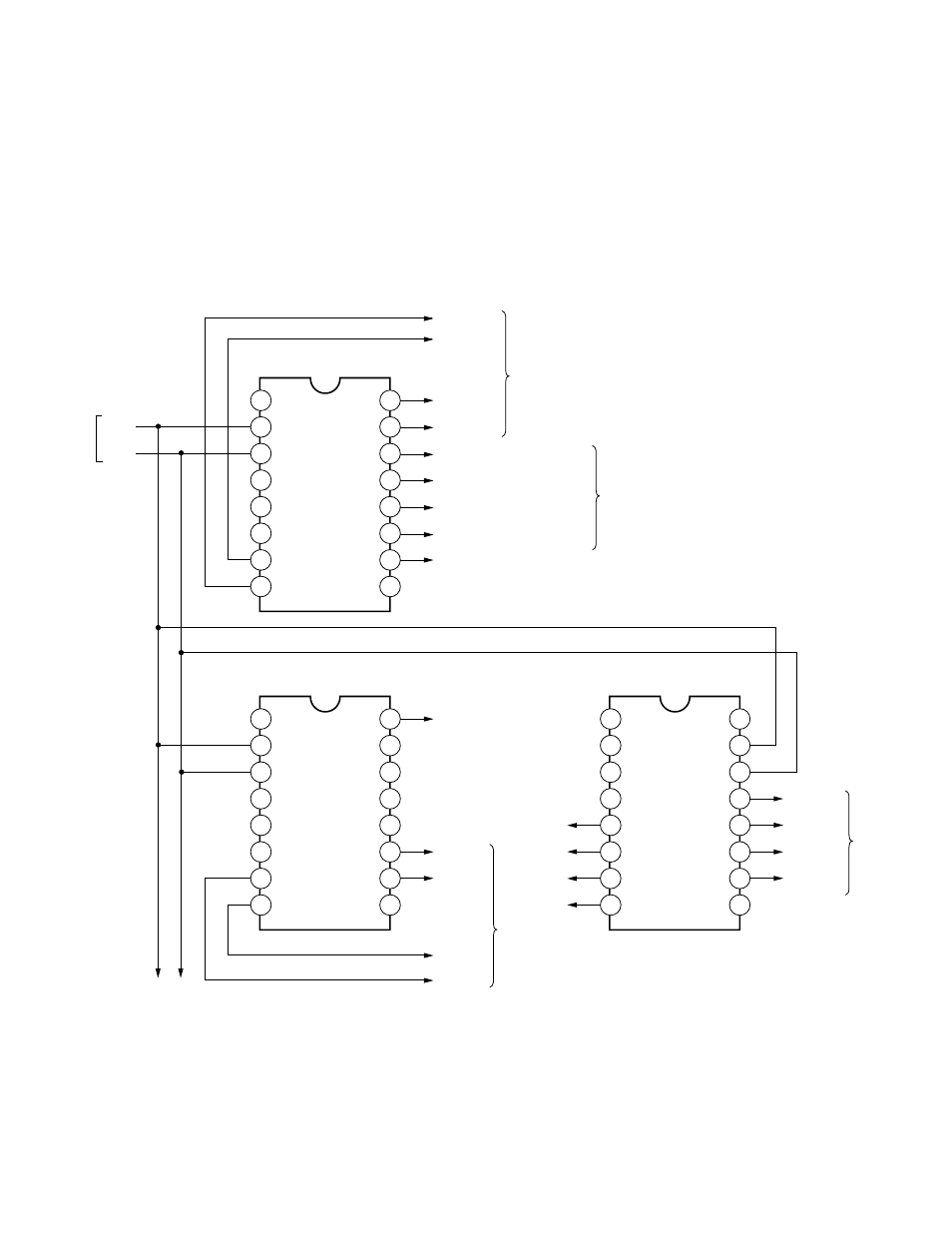
7-5. Microprocessor Interface
The peripheral block diagram of the microprocessor
shows in Fig. 7-5-1. All kinds of control such as signal
SW, etc. are carried out by the I
2
C of microprocessor. The
level control of RGB signal process IC (QB024:
M52320SP) and the sync polarity information of the
sync process IC (QB012: M52347FP) are carried out in
QB025 (CXA1315M). Refer to table 7-5-1 for the logic
about the polarity information of sync signal.
RGB/VIDEO SW, Audio mute/volume adjustment, etc.
are controlled in QV045 (CXA1315M). Further, using
camera or not, camera zoom and focus adjustment
controls are carried out in QV057.
Fig. 7-5-1
16
1
15
2
14
3
13
4
12
5
11
6
10
7
9
8
SW1
SW0
DAC4
DAC3
DAC2
DAC1
DAC0
GND
Vcc
SCL
SDA
SAD2
SAD1
SAD0
SW3
SW2
16
1
15
2
14
3
13
4
12
5
11
6
10
7
9
8
SW1
SW0
DAC4
DAC3
DAC2
DAC1
DAC0
GND
Vcc
SCL
SDA
SAD2
SAD1
SAD0
SW3
SW2
H. STATE
V. STATE
H. POL
V. POL
M52347FP
G SUB CONTRAST
B SUB CONTRAST
BRIGHT ADJUST
MAIN CONTRAST ADJUST
R SUB CONTRAST
MUTE
RGB/VIDEO
SW
VOL
ENABLE
SELECT
M52320SP
PV013
QB025
CXA1315M
QV045
CXA1315M
16
1
15
2
14
3
13
4
12
5
11
6
10
7
9
8
SO
SCL
SDA
D0
D1
D2
D3
GND
FIL/SW
VDET
SYUSEN
CAMON1
CS0
CS1
CS2
Vcc
D7
D6
D5
D4
ZOOM +
ZOOM -
FOCUS +
FOCUS -
QV057
M62320FP
SCL
From
Microprocessor
SDA