Toshiba TLP511E User Manual
Page 27
6-6
6-2-6. Picture Size of View Conversion IC T-FORC
(QX204, QX404, QX604)
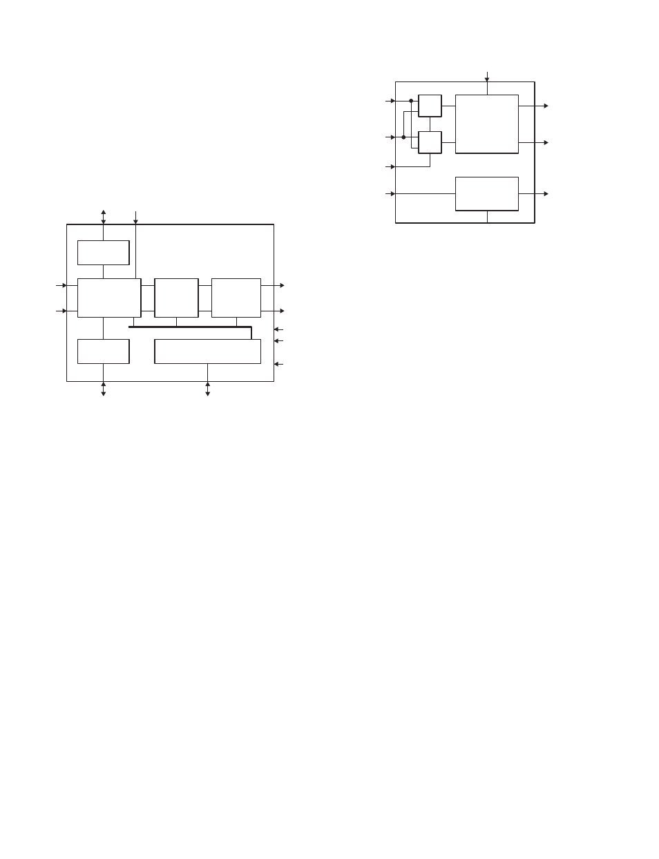
A configuration of T-FORC is shown in Fig. 6-2-5. The
T-FORC is a newly developed picture size conversion IC.
By using the IC, smooth picture enlargement and
reduction, and format conversion will be made. Also, a
gamma correction circuit is built in the IC.
Fig. 6-2-5
6-2-7. Memory
The memory uses four general 4 M bits EDO-DRAMs
(256k
x 16 bits) per 1 channel.
6-2-8. Exchange PLD
A configuration of timing signal generation PLD is
shown in Fig. 6-2-6. In the unit, the signal process is
carried out in parallel by dividing the process into two
systems. In order to reduce the characteristic difference
between these two systems, the signals of both systems
are switched for every 1 line and 1 frame. The PLD
carries out the process. Also, the ON-SCREEN display
signal superimposing, addition of non-display section for
top and bottom and left and right, etc. are carried out by
the PLD.
Memory
Freeze
MEMORY
INTERFACE
FORMAT
CONVERTER
GAMMA
(LOOK UP
TABLE)
OSD SW
BLK SW
(NOT USED)
BUS
INTERFACE
Memory
MPU
Input CLK
System CLK
(42 MHz)
Panel CLK
(32.5 MHz)
MEMORY
INTERFACE
OSD, OSDI, PBLK
Video
signal
Video
signal
Video
signal
Video
signal
SEL
From
timing PLD
SW
SW
OSD SW
BLANKING SW
PANEL TIMING
TRIM
To LCD panel
(ENB, DX)
MPU
Fig. 6-2-6
6-2-9. D/A Converter
MB40950 is a 10 bits 3 channels D/A converter of which
max. conversion speed is 60 MHz. In order to reduce the
difference of two systems of each RGB channel, each
RGB channel possesses one IC respectively. So one
channel of 3 channels D/A converter built in the IC is not
used. The output signal level ranges from 3.0 to 5.0V.