2. input signal switch section -3 – Toshiba TLP511E User Manual
Page 30
7-3
25
26
9
11
3
5
6
34
31
29
37
39
13
14
33
32
QV005
TDA9141
Y2
C2
S2
LEV
REV
Y3
SCL
L OUT 1
C OUT 1
Y OUT 1
V OUT 1
Y IN 1
C IN 1
AUDIO
Microprocessor
R OUT 1
SDA
C3
L
R
Y
S1/S2
C
Y
C
CAMERA
S
RGB
AUDIO
44
46
LV1
RV1
L
R
VIDEO
AUDIO
43
45
V1
Y1
VIDEO
COMB
FILTER
QV001
CXA1855Q
QV002
TC9090AN
7-2. Input Signal Switch Section
The signal SW section works as a circuit to supply the
signal to the signal process section in the next stage and
each output terminal by switching the signal entered
(video, audio).
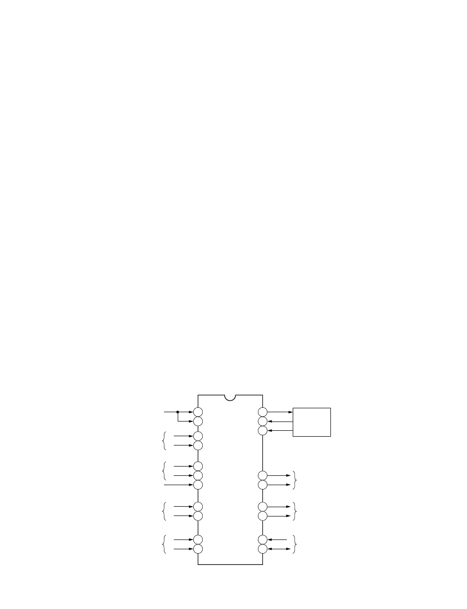
Each input signal is sent to QV001 (CXA1855Q) as
shown in Fig. 7-2-1. The IC control is carried out by I
2
C
bus.
7-2-1. Video Signal
The composite video signal enters pins 43 (V1) and 45
(Y1) at the same time. When the composite signal
entered is a NTSC/PAL color signal, pin 43 (V1) is
selected. When it is either a SECAM or Black & White
signal and when the input switching is carried out, pin
45 (Y1) is selected.
This is because the composite signal is supplied to the
video/color process IC in the next stage passing through
the Y/C separation IC QV002 (TC9090AN) when the
composite signal is either SECAM or black & white
signal and when the input switching is carried out.
This is also because in the Y/C separation IC QV002
(TC9090AN), the SECAM signal cannot be separated
into Y and C signals, and it is not necessary for the Black
& White signal to be separated in Y and C signals.
The signal developed from pin 34 is Y/C-separated by Y/
C separation IC QV002 (TC9090AN) and then enters the
signal SW IC QV001 (CXA1855Q) again. (Pin 31 (Y),
pin 29 (C))
The Y/C signals entered from S terminal enter pins 3 and
5 respectively.
In case of TLP511, the video signal from the camera
section is supplied as Y/C signals and enters pins 9 and
11 respectively.
The video signal selected finally develops from pins 37
(Y) and 29 (C) respectively.
7-2-2. Audio Signal
The audio signal employs two input systems; one is for
video signal and the other is for RGB signals. Each
system is applicable to L and R stereo inputs respec-
tively.
The audio signal for the video signal is selected when
the video signal is selected and the audio signal for RGB
signals is selected when the RGB signals are selected.
The audio signal selected develops from pins 33 (L) and
32 (R).
7-2-3. RGB Signal
The RGB signals are entered using a high density D-SUB
15 and separated in two systems for the internal signal
process and the external output signal. The external
output signal develops at PV002 (RGB output connec-
tor) via QB007 (6 dB amp.). When the power turns on,
the RGB output signals always develop if any signal
enters at the RGB input terminal.
On the other hand, the internal process signals for the
RGB signals enter QB004, QB005 and QB006, respec-
tively. The input signal switch IC controls to mute the
RGB input signals when selecting the video input.
Fig. 7-2-1