4 dm area allocations, Dm area allocations, Nd 4-4 dm area allocations – Omron W343-E1-07 User Manual
Page 94
73
DM Area Allocations
Section 4-4
4-4
DM Area Allocations
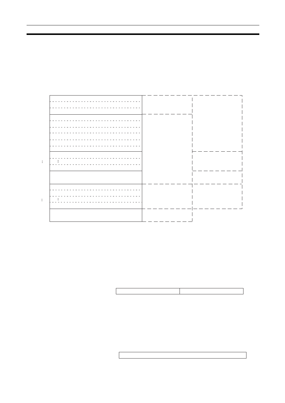
The various kinds of data are stored in the offset positions shown in the fol-
lowing diagram, from the beginning word in the area for each Unit.
The beginning word m is calculated by the following equation:
Beginning word m = D30000 + (100 x unit number)
Note For CS-series Ethernet Units, this area is the IP Address Display Area and
data in this area can be transferred from the Ethernet Unit to the CPU Unit
only. For CJ-series Ethernet Units, this area is the IP Address Display/Setting
Area and data in this area can be transferred in either direction.
The meanings of the items shown in the above diagram are explained on the
following pages. For details regarding the related communications services
shown in the diagram, refer to the indicated sections.
Internode Test Remote Network Address and Node Number (CPU Unit to Ethernet Unit)
Specify the remote network address and node number in hexadecimal within
the following ranges:
Remote network address: 00 to 7F Hex (0 to 127 decimal)
Remote node number: 01 to 7E Hex (0 to 126 decimal)
If a remote network address is set to 00, it will specify the local network (i.e.,
the network to which the Ethernet Unit is connected.)
Internode Test Number of Send Bytes (CPU Unit to Ethernet Unit)
Offset
Bit
Data direction
Related communications services
CPU Unit to Ethernet Unit
Ethernet Unit to CPU Unit
CPU Unit to Ethernet Unit
m
m+1
m+2
m+3
m+4
m+5
m+6
m+7
m+8
m+9
m+16
m+17
m+18
m+28
m+88
m+98
m+99
15
8
7
0
Internode test remote network address and node number
Internode test number of send bytes
Internode test response monitoring time
Internode test status
Number of internode test runs
Number of internode test timeout errors
Number of internode test response errors
Number of internode test send errors
Number of times internode test data did not match
TCP socket No. 1 connection status
TCP socket No. 8 connection status
Mail status
Socket Services Parameter Area 1
Socket Services Parameter Area 2
Socket Services Parameter Area 8
IP Address Display/Setting Area (See note.)
Mail function
Internode Test Function
Socket Services
Socket Services
Ethernet Unit to CPU Unit or
CPU Unit to Ethernet Unit
(Refer to 9-3 Internode Test.)
(Refer to Section 6
Socket Services.)
(Refer to Section 6
Socket Services.)
Remote network address
Remote node number
15 14 13 12 11 10 9
8
7
6
5
4
3
2
1
0
m
Number of send bytes (0000 to 07CC Hex)
15 14 13 12 11 10 9
8
7
6
5
4
3
2
1
0
m+1