2-5 application procedure, Application procedure, Procedure – Omron W343-E1-07 User Manual
Page 147
126
Using Socket Services with Socket Service Request Switches
Section 6-2
Note The TCP socket connection status is also provided as codes in the following
words of the words allocated to the Ethernet Unit in the CPU Bus Unit Area in
the DM Area: D30000 + (100 x unit number) +9 to +16. Refer to TCP Socket
Connection Status on page 75 and to Appendix D TCP Status Transitions for
details.
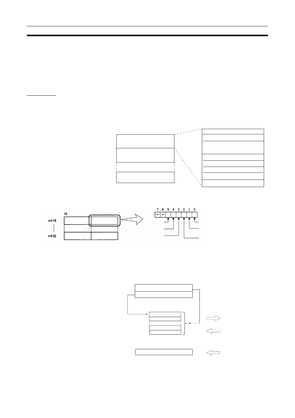
6-2-5
Application Procedure
Procedure
1,2,3...
1.
Set the socket service parameters in the CPU Bus Unit Area in the DM Ar-
ea.
2.
Turn ON the Socket Service Request Bits in the CPU Bus Unit Area in the
CIO Area.
3.
When a send or receive request is made, the data will be automatically
sent or received according to the send/receive data address in the Socket
Service Parameter Area. When processing has been completed, a re-
sponse code will be automatically stored in the Socket Service Parame-
ters.
Remote UDP/TCP port No.
Number of bytes to send/receive
Send/Receive data address
Parameters
m = D30000 + (100 x unit number)
CPU Bus Unit Area in the DM Area
Socket Service Parameter Area 1
Socket Service Parameter Area 8
Socket Service Parameter Area 2
Time out time
Response code
UDP/TCP socket No.
Local UDP/TCP port No.
Remote IP address
15
0
m+18
m+28
m+88
Socket Service
Request Switches 7
Socket Service
Request Switches 1
Socket Service
Request Switches 8
Socket Service
Request Switches 2
CPU Bus Unit Area in the CIO Area
Close Request
Switch
Receive Request Switch
Send Request Switch
UDP Open Request Switch
TCP Passive Open Request Switch
TCP Active Open Request Switch
Number of bytes to send/receive
Send/receive data address
I/O memory
Send
or
Receive
Response code
Stored