2 system configuration, 2-1 device configuration, 2-2 node connections – Omron W343-E1-07 User Manual
Page 24: System configuration, Device configuration, Node connections
3
System Configuration
Section 1-2
1-2
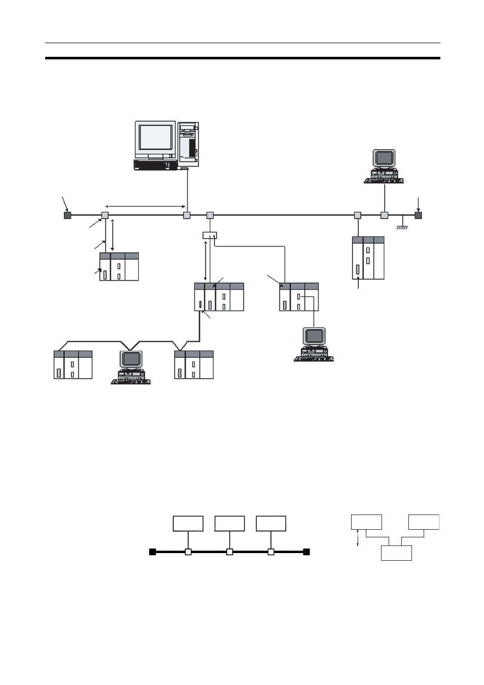
System Configuration
1-2-1
Device Configuration
Note
1.
Transmission distance (from Terminator to Terminator):
500 meters/segment max.
2.
When segments are indirectly connected by a repeater: 2.5 km/network
3.
Node interval (from transceiver to transceiver): Integral multiples of 2.5 m
4.
Transceiver cable length: 50 m max.
1-2-2
Node Connections
Minimal Configuration: 1 Segment
Workstation or personal computer
CX-Programmer
Terminator
Between nodes:
Integral multiples of 2.5 m
Transceiver
Transceiver cable
50 m max.
CS-series PC
Controller Link network
C200HX/HG/HE PC
CS1W-ETN01
Ethernet Unit
(10Base-5)
Ethernet (10 Mbps)
500 m/segment max.
10Base-5 coaxial cable
(or 10Base-T twisted-pair cable)
Terminator
CS1W-ETN11
Ethernet Unit
(10Base-T)
CVM1/CV-series
PC
CVM1/CV Ethernet Unit
(10Base-5)
CX-Programmer
CS-series
PC
CS-series PC
FA computer
CS-series Controller Link Unit
Ground
100 m max.
CJ-series
PC
CJ1W-ETN11
Ethernet Unit
(10Base-T)
CS-series
CS-series
CJ-series
Node
Node
Node
10Base-5
10Base-T
Node
Node
Hub
1 segment