2-2 response codes, Response codes, Time out time – Omron W343-E1-07 User Manual
Page 138: Number of bytes to send/receive, Send/receive data address
117
Using Socket Services with Socket Service Request Switches
Section 6-2
Remote UDP/TCP Port No.
Specify the UDP or TCP port number used by the remote device.
• This parameter is not used when making a receive request for a UDP
socket. The remote UDP/TCP port number will be stored with the
response data and will be written as the Remote UDP/TCP Port No. in the
Socket Service Parameter Area.
• When opening a passive TCP socket, the combination of the remote IP
address and the remote TCP port number can be used to affect process-
ing as shown in the table for the Remote IP Address, above. If the Remote
UDP/TCP Port No. is set to 0, the UDP/TCP port number of the remote
device will be written as the Remote UDP/TCP Port No. in the Socket Ser-
vice Parameter Area.
Time Out Time
Set the time limit in units of 0.1 s for completion of communications from the
time that the Receive Request Switch (TCP or UDP) or the TCP Passive
Open Request Switch is turned ON. A response code of 0080 Hex (timeout)
will be stored if communications time out. If 0 is set, the requested service will
not be timed.
Number of Bytes to Send/Receive
Send the number of bytes to be sent or the number of bytes to receive. When
the transfer has been completed, the actual number of bytes that have been
sent or received will be written here.
Send/Receive Data Address
Specify the address of the first word to send or the address of the first word
where data is to be received. Always set the bit number to 00 Hex.
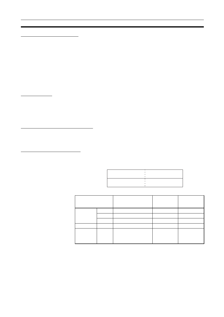
The following specifications can be used.
6-2-2
Response Codes
When processing of a request has been completed for socket services exe-
cuted using Socket Service Request Switches, a response code will be stored
in the Response Code word in the Socket Service Parameter Area. The fol-
Area
Word address
Area
designation
(Hex)
Word address
(Hex)
CIO, HR,
and AR
Areas
CIO
0000 to 6143
B0
0000 to 17FF
HR
H000 to H511
B2
0000 to 01FF
AR
A448 to A959
B3
01C0 to 03BF
DM Area
DM
D00000 to D32767
82
0000 to 7FFF
EM Area
Bank 0
E0_00000 to E0_32767
A0
0000 to 7FFF
:
:
:
:
Bank C
EC_00000 to EC_32767 AC
0000 to 7FFF
Offset
Area
designation
Leftmost 2 digits
of word address
Rightmost 2 digits
of word address
Bit number
(always 00 Hex)
15
8
7
0
+6
+7