Using a delay from sample clock to convert clock, Figure 4-9. ai sample clock and ai convert clock, Other timing requirements – National Instruments Data Acquisition Device NI USB-621x User Manual
Page 50
Chapter 4
Analog Input
© National Instruments Corporation
4-17
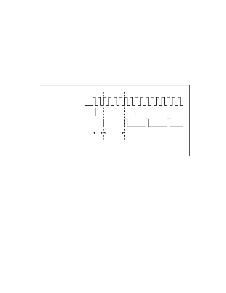
Using a Delay from Sample Clock to Convert Clock
When using an internally generated AI Convert Clock, you also can specify
a configurable delay from AI Sample Clock to the first AI Convert Clock
pulse within the sample. By default, this delay is three ticks of AI Convert
Clock Timebase.
Figure 4-9 shows the relationship of AI Sample Clock to AI Convert Clock.
Figure 4-9. AI Sample Clock and AI Convert Clock
Other Timing Requirements
The sample and conversion level timing of USB-621x devices work such
that clock signals are gated off unless the proper timing requirements are
met. For example, the device ignores both AI Sample Clock and AI
Convert Clock until it receives a valid AI Start Trigger signal. Once the
device recognizes an AI Sample Clock pulse, it ignores subsequent AI
Sample Clock pulses until it receives the correct number of AI Convert
Clock pulses.
Similarly, the device ignores all AI Convert Clock pulses until it recognizes
an AI Sample Clock pulse. Once the device receives the correct number of
AI Convert Clock pulses, it ignores subsequent AI Convert Clock pulses
until it receives another AI Sample Clock. Figures 4-10, 4-11, 4-12,
and 4-13 show timing sequences for a four-channel acquisition (using AI
channels 0, 1, 2, and 3) and demonstrate proper and improper sequencing
of AI Sample Clock and AI Convert Clock.
AI Convert Clock Timebase
AI Sample Clock
AI Convert Clock
Delay
From
Sample
Clock
Convert
Period