Figure 8-9. buffered semi-period measurement, Frequency measurement, Frequency measurement -9 – National Instruments Data Acquisition Device NI USB-621x User Manual
Page 102
Chapter 8
Counters
© National Instruments Corporation
8-9
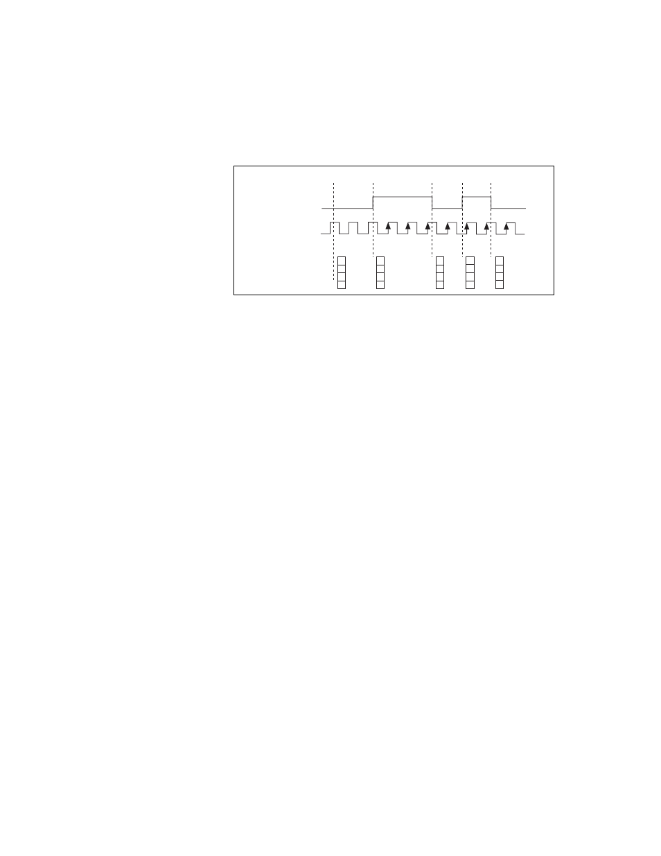
Figure 8-9 shows an example of a buffered semi-period measurement.
Figure 8-9. Buffered Semi-Period Measurement
Note that if you are using an external signal as the Source, at least one
Source pulse should occur between each active edge of the Gate signal.
This condition ensures that correct values are returned by the counter. If this
condition is not met, the counter returns a zero. Refer to the
section for more information.
For information about connecting counter signals, refer to the
section.
Frequency Measurement
You can use the counters to measure frequency in several different ways.
You can choose one of the following methods depending on your
application:
•
Method 1: Measure Low Frequency with One Counter—In this
method, you measure one period of your signal using a known
timebase. This method is good for low frequency signals.
You can route the signal to measure (F1) to the Gate of a counter. You
can route a known timebase (Ft) to the Source of the counter. The
known timebase can be 80MHzTimebase. For signals that might be
slower than 0.02 Hz, use a slower known timebase.
3
1
2
3
1
3
SOURCE
GATE
Counter Value
Buffer
1
3
2
2
1 1
1
3
1
2
0
Counter Armed