Figure 8-17. channel z reload with x4 decoding, Measurements using two pulse encoders, Figure 8-18. measurements using two pulse encoders – National Instruments Data Acquisition Device NI USB-621x User Manual
Page 110: Measurements using two pulse encoders -17
Chapter 8
Counters
© National Instruments Corporation
8-17
high during at least a portion of the phase you specify for reload. For
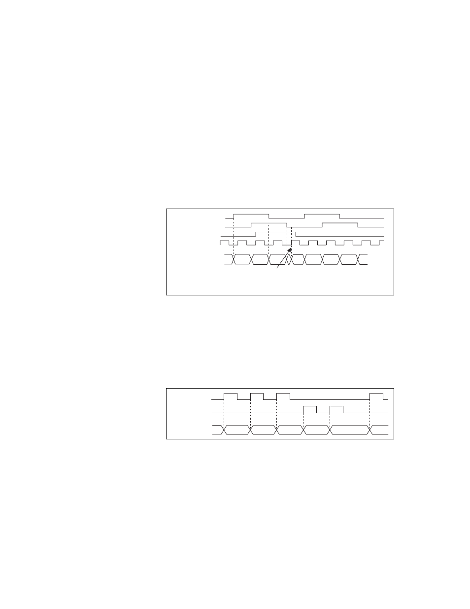
instance, in Figure 8-17, channel Z is never high when channel A is high
and channel B is low. Thus, the reload must occur in some other phase.
In Figure 8-17, the reload phase is when both channel A and channel B are
low. The reload occurs when this phase is true and channel Z is high.
Incrementing and decrementing takes priority over reloading. Thus, when
the channel B goes low to enter the reload phase, the increment occurs first.
The reload occurs within one maximum timebase period after the reload
phase becomes true. After the reload occurs, the counter continues to count
as before. The figure illustrates channel Z reload with X4 decoding.
Figure 8-17. Channel Z Reload with X4 Decoding
Measurements Using Two Pulse Encoders
The counter supports two pulse encoders that have two channels—channels
A and B.
The counter increments on each rising edge of channel A. The counter
decrements on each rising edge of channel B, as shown in Figure 8-18.
Figure 8-18. Measurements Using Two Pulse Encoders
For information about connecting counter signals, refer to the
section.
Ch A
Ch B
Counter Value
5 6
A = 0
B = 0
Z = 1
Ch Z
Max Timebase
8 9 0
2
1
7 4
3
Ch A
Ch B
Counter Value 2
3 5
4
3
4 4