Figure 7-29. pulse generation for ets, Counter timing signals, Counter timing signals -25 – National Instruments Network Device DAQ S User Manual
Page 97
Chapter 7
Counters
© National Instruments Corporation
7-25
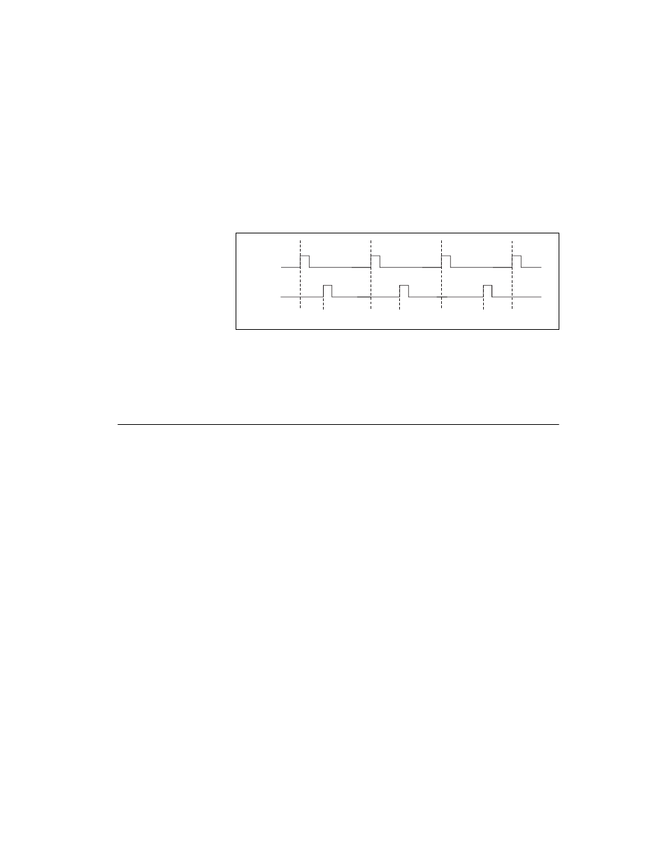
The waveform thus produced at the counter’s output can be used to provide
timing for undersampling applications where a digitizing system can
sample repetitive waveforms that are higher in frequency than the Nyquist
frequency of the system. Figure 7-29 shows an example of pulse generation
for ETS; the delay from the trigger to the pulse increases after each
subsequent Gate active edge.
Figure 7-29. Pulse Generation for ETS
For information about connecting counter signals, refer to the
section.
Counter Timing Signals
S Series devices feature the following counter timing signals:
•
•
•
•
•
•
•
•
•
Counter n Internal Output Signal
•
•
In this section, n refers to either Counter 0 or 1. For example, Counter n
Source refers to two signals—Counter 0 Source (the source input to
Counter 0) and Counter 1 Source (the source input to Counter 1).
OUT
D1
D2 = D1 +
Δ
D D3 = D1 + 2
Δ
D
GATE