Chapter 3 i/o connector, Ni 6124 i/o connector signal descriptions, Table 3-1. ni 6124 device signal descriptions – National Instruments Network Device DAQ S User Manual
Page 25: Ni 6124 i/o connector signal descriptions -1, I/o connector
© National Instruments Corporation
3-1
3
I/O Connector
This chapter contains information about the S Series I/O connector. Refer
to one of the following sections, depending on your device:
•
NI 6124 I/O Connector Signal Descriptions
•
NI 6154 I/O Connector Signal Descriptions
Refer to Appendix A,
, for the I/O connector
pinout for your device.
NI 6124 I/O Connector Signal Descriptions
(NI 6124 Only)
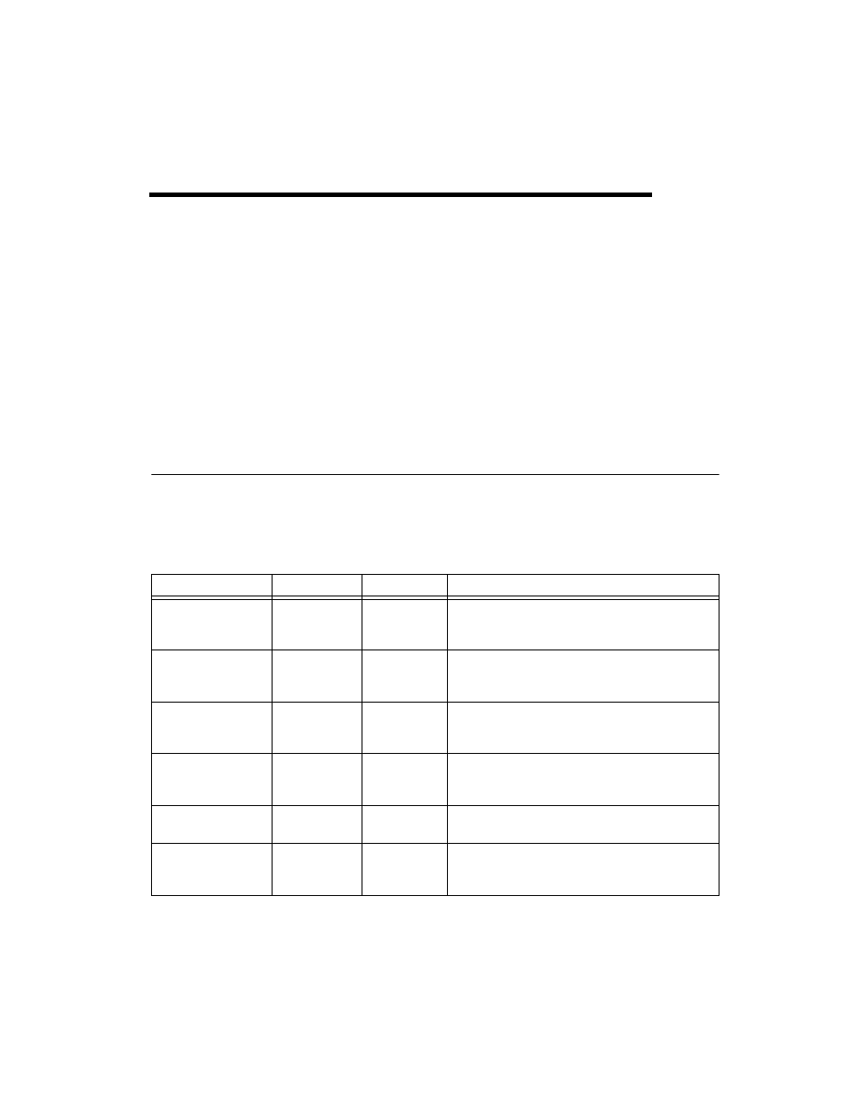
Table 3-1 describes the signals found on the NI 6124 I/O
connector. For more information about these signals, refer to the NI 6124
Specifications.
Table 3-1. NI 6124 Device Signal Descriptions
I/O Connector Pin
Reference
Direction
Signal Description
AI <0..3> GND
—
—
Analog Input Channels 0 through 3 Ground—These
pins are the bias current return point for differential
measurements.
AI <0..3> +
AI <0..3> GND
Input
Analog Input Channels 0 through 3 (+)—These pins
are routed to the (+) terminal of the respective channel
amplifier.
AI <0..3> –
AI <0..3> GND
Input
Analog Input Channels 0 through 3 (–)—These pins
are routed to the (–) terminal of the respective channel
amplifier.
AO <0..1>
AO GND
Output
Analog Output Channels 0 through 1—These pins
supply the voltage output of analog output channels 0
and 1.
AO GND
—
—
Analog Output Ground—The AO voltages and the
external reference voltage are referenced to these pins.
D GND
—
—
Digital Ground—These pins supply the reference for the
digital signals at the I/O connector and the +5 VDC
supply.