Pfi for isolated devices, Pfi for isolated devices -2 – National Instruments Network Device DAQ S User Manual
Page 113
Chapter 8
Programmable Function Interfaces (PFI)
8-2
ni.com
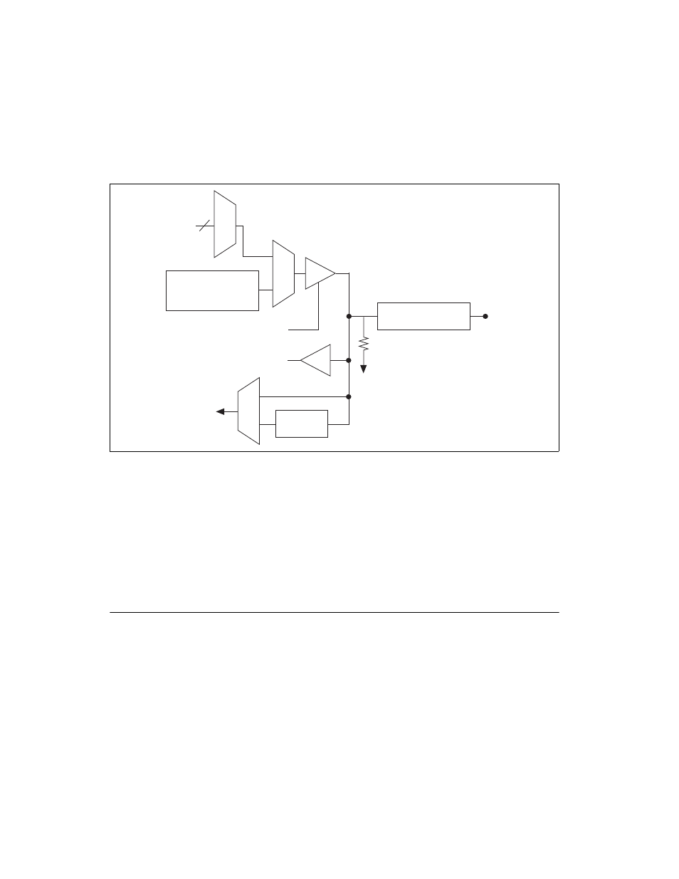
Each PFI input also has a programmable debouncing filter. Figure 8-1
shows the circuitry of one PFI line. Each PFI line is similar.
Figure 8-1. PFI Circuitry on Non-Isolated S Series Devices
When a terminal is used as a timing input or output signal, it is called PFI x
(where x is an integer from 0 to 15). When a terminal is used as a static
digital input or output, it is called P1.x or P2.x. On the I/O connector, each
terminal is labeled PFI x/P1.x or PFI x/P2.x.
The voltage input and output levels and the current drive levels of the PFI
signals are listed in the NI 6124 Specifications.
PFI for Isolated Devices
(NI 6154 Only)
Isolated S Series devices have 10 Programmable Function
Interface (PFI) signals—six input signals and four output signals.
Each PFI <0..5>/P0.<0..5> can be configured as a timing input signal for
AI or counter/timer functions or a static digital input. Each PFI input also
has a programmable debouncing filter.
Timing Signals
Direction Control
Static DI
I/O Protection
Weak Pull-Down
PFI x/P1 or
PFI x/P2
Static DO
Buffer
To Input Timing
Signal Selectors
PFI
Filters