Ni 6154 i/o connector signal descriptions, Ni 6154 i/o connector signal descriptions -2 – National Instruments Network Device DAQ S User Manual
Page 26
Chapter 3
I/O Connector
3-2
ni.com
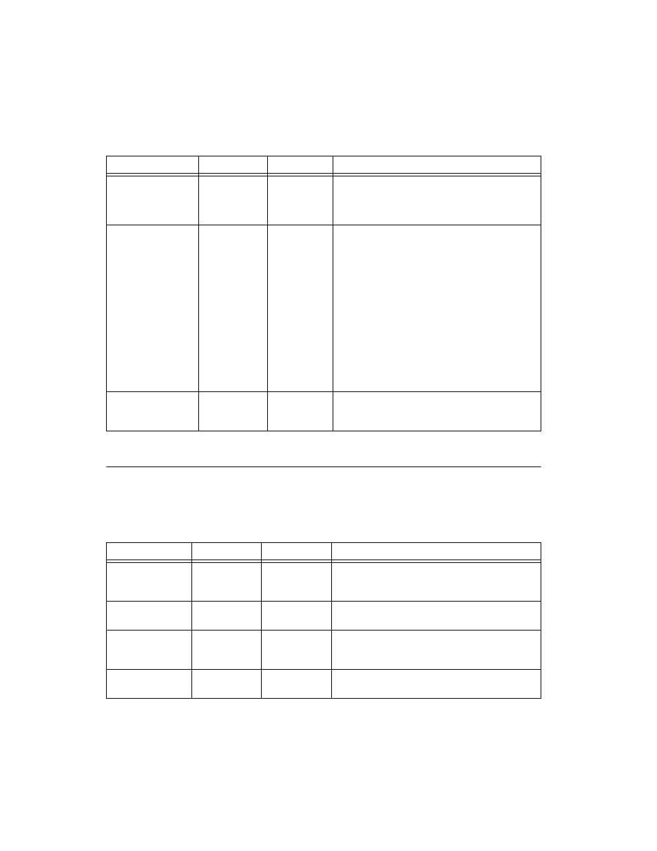
NI 6154 I/O Connector Signal Descriptions
(NI 6154 Only)
Table 3-2 describes the signals found on the NI 6154 I/O
connector. For more information about these signals, refer to the NI 6154
Specifications.
P0.<0..7>
D GND
Input or Output
Digital I/O Channels 0 through 7—You can
individually configure each signal as an input or output.
P0.6 and P0.7 can also control the up/down signal of
Counters 0 and 1, respectively.
PFI <0..7>/P1.<0..7>
PFI <8..15>/P2.<0..7>
D GND
Input or Output
Programmable Function Interface or Digital I/O
Channels 0 through 7 and Channels 8 through
15—Each of these terminals can be individually
configured as a PFI terminal or a digital I/O terminal.
As an input, each PFI terminal can be used to supply an
external source for AI, AO, DI, and DO timing signals or
counter/timer inputs.
As a PFI output, you can route many different internal AI,
AO, DI, or DO timing signals to each PFI terminal. You
also can route the counter/timer outputs to each PFI
terminal.
As a Port 1 or Port 2 digital I/O signal, you can
individually configure each signal as an input or output.
+5 V
D GND
Output
+5 Power Source—These pins provide +5 V power. For
more information, refer to the
section.
Table 3-2. NI 6154 I/O Connector Signal Descriptions
I/O Connector Pin
Reference
Direction
Signal Description
AI <0..3> +
AI <0..3> –
Input
Analog Input Channels 0 through 3 (+)—These pins are
routed to the (+) terminal of the respective channel
amplifier.
AI <0..3> –
—
Input
Analog Input Channels 0 through 3 (–)—The reference
pins for the corresponding AI <0..3> + pin.
AO <0..3> +
AO <0..3> –
Output
Analog Output Channels 0 through 3 (+)—These pins
supply the voltage output of Analog Output channels 0
through 3.
AO <0..3> –
—
Output
Analog Output Channels 0 through 3 (–)—The
reference pins for the corresponding AO <0..3> + pin.
Table 3-1. NI 6124 Device Signal Descriptions (Continued)
I/O Connector Pin
Reference
Direction
Signal Description