Static dio for non-isolated devices, Static dio for non-isolated devices -2 – National Instruments Network Device DAQ S User Manual
Page 61
Chapter 6
Digital I/O
6-2
ni.com
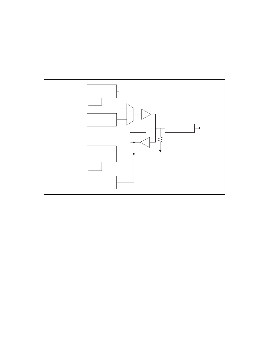
Figure 6-1 shows the circuitry of one DIO line. Each DIO line is similar.
The following sections provide information about the various parts of the
DIO circuit.
Figure 6-1. Non-Isolated S Series Digital I/O Circuitry
The DIO terminals are named P0.<0..7> on the device I/O connector.
The voltage input and output levels and the current drive levels of the DIO
lines are listed in the specifications of your device.
Static DIO for Non-Isolated Devices
(NI 6124 Only)
Each DIO line can be used as a static DI or DO line. You can
use static DIO lines to monitor or control digital signals. Each DIO can be
individually configured as a digital input (DI) or digital output (DO).
All samples of static DI lines and updates of DO lines are software-timed.
P0.6 and P0.7 on these devices also can control the up/down input of
general-purpose counters 0 and 1, respectively. However, it is
recommended that you use PFI signals to control the up/down input of the
counters. The up/down control signals, Counter 0 Up_Down and Counter 1
Up_Down, are input-only and do not affect the operation of the DIO lines.
DO Sample Clock
DO Waveform
Generation FIFO
DO.x Direction Control
Static DI
DI Sample Clock
DI Change
Detection
I/O Protection
Weak Pull-Down
P0.x
Static DO
Buffer
DI Waveform
Measurement
FIFO