National Instruments Network Device DAQ S User Manual
Page 114
Chapter 8
Programmable Function Interfaces (PFI)
© National Instruments Corporation
8-3
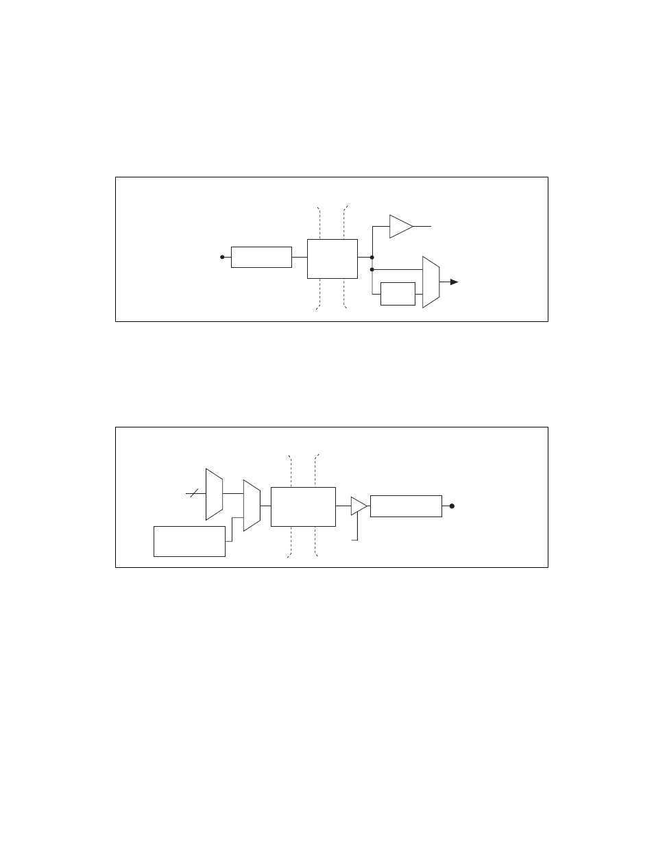
Figure 8-2 shows the circuitry of one PFI input line. Each PFI line is
similar.
Figure 8-2. PFI Input Circuitry on Isolated S Series Devices
Each PFI <6..9>/P1.<0..3> can be configured as a timing output signal
from AI or counter/timer functions or a static digital output.
Figure 8-3 shows the circuitry of one PFI output line. Each PFI line is
similar.
Figure 8-3. PFI Output Circuitry on Isolated S Series Devices
When a terminal is used as a timing input or output signal, it is called PFI x
(where x is an integer from 0 to 9). When a terminal is used as a static digital
input or output, it is called P0.x or P1.x.
The voltage input and output levels and the current drive levels of the PFI
signals are listed in the NI 6154 Specifications.
To Input Timing
Signal Selectors
Isolation
Barrier
Digital
Isolators
I/O Protection
PFI <0..5>/P0.<0..5>
PFI
Filters
Static DI
Timing Signals
I/O Protection
PFI <6..9>/P1.<0..3>
Output
Enable
Static DO
Buffer
Isolation
Barrier
Digital
Isolators
Note
: One output enable is shared
by all digital output signals.