Connecting pfi input signals, Figure 8-4. pfi input signals connections, Pfi filters – National Instruments Network Device DAQ S User Manual
Page 117: Connecting pfi input signals -6 pfi filters -6
Chapter 8
Programmable Function Interfaces (PFI)
8-6
ni.com
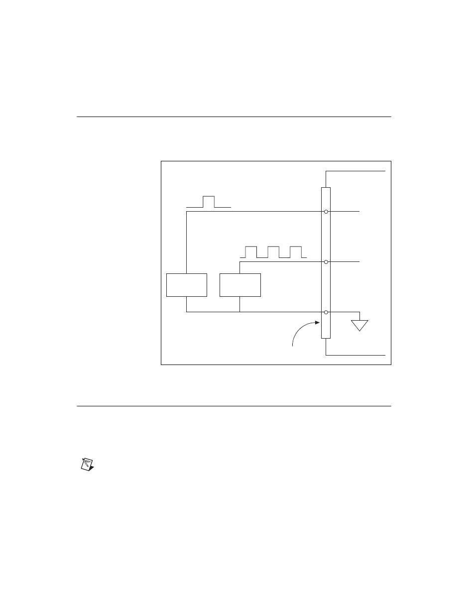
Connecting PFI Input Signals
All PFI input connections are referenced to D GND. Figure 8-4 shows this
reference, and how to connect an external PFI 0 source and an external
PFI 2 source to two PFI terminals.
Figure 8-4. PFI Input Signals Connections
PFI Filters
You can enable a programmable debouncing filter on each PFI, RTSI, or
PXI_STAR signal. When the filters are enabled, your device samples the
input on each rising edge of a filter clock. These S Series devices use an
onboard oscillator to generate the filter clock with a 40 MHz frequency.
Note
NI-DAQmx only supports filters on counter inputs.
The following is an example of low to high transitions of the input signal.
High to low transitions work similarly.
PFI 0
Source
PFI 2
Source
S Series Device
D GND
PFI 2
PFI 0
I/O Connector
- Instrument Driver NI-DMM (12 pages)
- 24-Bit Half/Full-Bridge Analog Input Module NI 9237 (36 pages)
- NI PXIe-8105 (76 pages)
- PXI NI 5401 (60 pages)
- Fieldpoint CFP-2210 (38 pages)
- NI 781xR (48 pages)
- NI 6233 (180 pages)
- 6508 PCI-DIO-96 (93 pages)
- PXI/CompactPCI Embedded Computer NI PXI-8108 (83 pages)
- NI 9233 (34 pages)
- NI USB-9219 (25 pages)
- GPIB-PC (262 pages)
- cFP-RTD-122 (15 pages)
- USB device 625x (23 pages)
- Isolated Analog Input Modules SCC-AI01 (18 pages)
- NI PCI-6111 (118 pages)
- NI USB-6008 (32 pages)
- PC-DIO-24 (75 pages)
- NI 9474 (31 pages)
- NI 6013 (109 pages)
- PXI-1428 (46 pages)
- NI PCI-5911 (51 pages)
- 2 SD Card Memory Module NI 9802 (16 pages)
- cFP-20xx (24 pages)
- NI USB-9234 (23 pages)
- NI 9871 (24 pages)
- Interface Device NI PCI-1426 (35 pages)
- AT E Series (184 pages)
- 9211A (19 pages)
- Module NI PXI-8250 (39 pages)
- 8330 Series (30 pages)
- NI PXIe-8360 (40 pages)
- Deterministic Ethernet Expansion Chassis NI 9144 (65 pages)
- NI 6509 (23 pages)
- NI MATRIXx Xmath (127 pages)
- NI 9481 (23 pages)
- Monochrome Image Acquisition Device NI 1410 (34 pages)
- VXI-1394 (74 pages)
- NI PXI-8104 (69 pages)
- NI 9235 (38 pages)
- 370620B-01 (17 pages)
- FP-RTD-124 (15 pages)
- VXI-USB (61 pages)
- NI PCI-8254R (45 pages)
- Interface Device NI PCI-8254R (16 pages)