Waveform generation timing signals, Figure 5-5. analog output engine routing options, Ao sample clock signal – National Instruments Network Device DAQ S User Manual
Page 54: Using an internal source, Waveform generation timing signals -6, Ao sample clock signal -6, Using an internal source -6
Chapter 5
Analog Output
5-6
ni.com
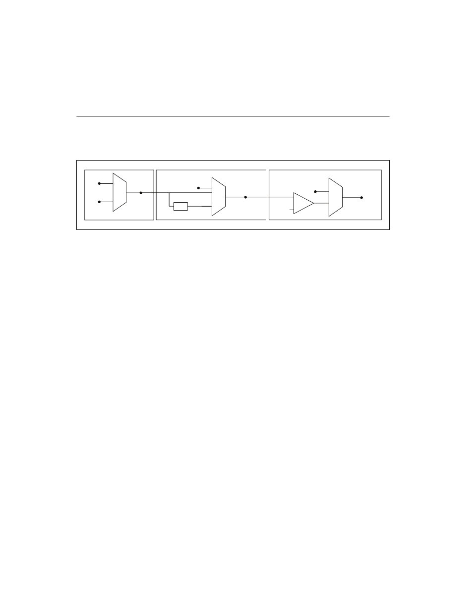
Waveform Generation Timing Signals
There is one AO Sample Clock that causes all AO channels to update
simultaneously. Figure 5-5 summarizes the timing and routing options
provided by the analog output timing engine.
Figure 5-5. Analog Output Engine Routing Options
S Series devices feature the following waveform generation timing signals:
•
AO Sample Clock Signal
•
AO Sample Clock Timebase Signal
•
•
AO Sample Clock Signal
You can use the AO Sample Clock (ao/SampleClock) signal to initiate
AO samples. Each sample updates the outputs of all of the DACs.
The source of the AO Sample Clock signal can be internal or external. You
can specify whether the DAC update begins on the rising edge or falling
edge of the AO Sample Clock signal.
Using an Internal Source
By default, AO Sample Clock is created internally by dividing down the
AO Sample Clock Timebase signal.
Several other internal signals can be routed to the sample clock. Refer to
Device Routing in MAX in the NI-DAQmx Help or the LabVIEW Help in
version 8.0 or later for more information.
RTSI 7
20 MHz
Timebase
÷
200
Master
Timebase
Onboard
Clock
PFI 0–9,
RTSI 0–6
ao/SampleClock
Timebase
Onboard
Clock
Divisor
ao/SampleClock
Ctr1InternalOutput
PFI 0–9,
RTSI 0–6
ч