Powerware 9335 User Manual
Page 65
Powerware 9335 (80 kVA and120 kVA) Installation and Operation
8-5
164201396 REV. A 071103
•
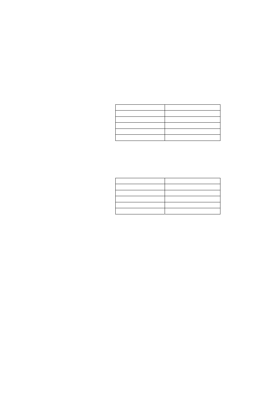
Rotate the Maintenance Bypass Switch IA1 to “I” (ON)
On LCD Display: “MANUAL BYP CLOSED” will appear and the LED
indicators will indicate as shown below:
LED Indicator
Color
LINE 1
Green
LINE 2
Green
BYPASS Green
INVERTER Red
BATTERY Green
2
) Simultaneously press both ON/OFF pushbuttons on the UPS cabinet control panel.
•
On the LCD Display: “LOAD OFF, SUPPLY FAILURE” will appear and the
LED indicators will indicate as shown below:
LED Indicator
Color
LINE 1
Green
LINE 2
OFF
BYPASS OFF
INVERTER OFF
BATTERY Flashing
Green
3) Rotate the Parallel Isolator Switch IA2 to “O” (OFF).
4) Open battery breakers in the external battery cabinet or racks
THE LOAD IS NOW SUPPLIED BY THE UTILITY MAINS AND IS NOT PROTECTED.