3 to operate a remote epo, Table 4 – 1. remote epo wire terminations, Table 4 – 2. remote epo – Powerware 9335 User Manual
Page 28
4-2
Powerware 9335 (80 kVA and 120 kVA) Installation and Operation
164201396 REV A 071103
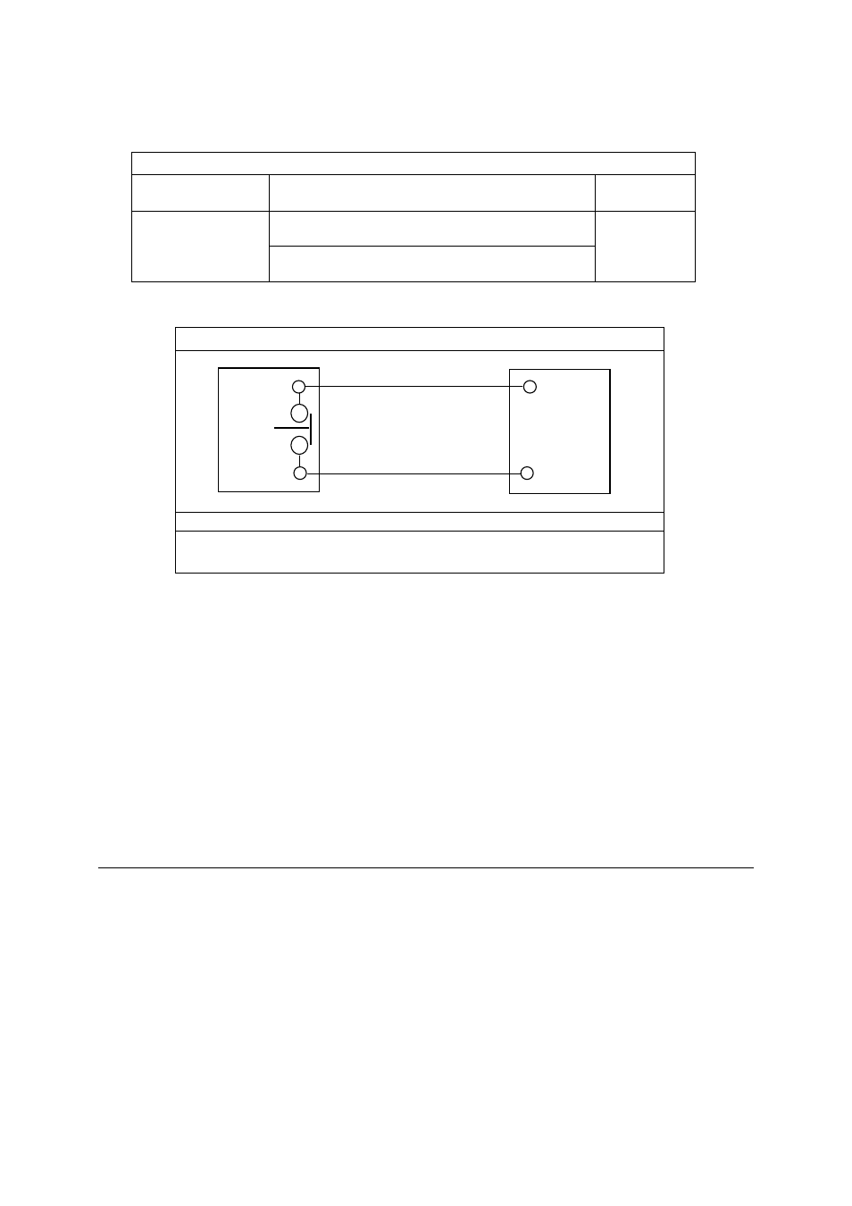
Table 4 – 1. Remote EPO Wire Terminations
From Remote
EPO Switch(s)
To X1 connector on front
of inner UPS panel
Remarks
X1 - 1
Refer to switch
manufacturers
installation
instructions
X1 - 2
Twisted
wires (2) 14-
18 gauge
Table 4 – 2. Remote EPO
Remote EPO switch rating is 24 VDC, 1 Amp maximum
NOTE: This switch must be a dedicated switch not tied into any
other circuits.
4. If you are installing multiple Remote EPO stations, wire additional stations in series
with the first Remote EPO.
5. If required, install appropriate sized conduit and wiring from the Remote EPO switch
to trip circuitry of upstream protective devices. A separate contact block, with the
appropriate normally open or normally closed contacts, must be used for this
function. Remote EPO switch wiring must be in accordance with UL Class 1
requirements.
6. Secure the UPS by reversing all steps taken to prepare it for Remote EPO
installation.
4.3 To Operate a Remote EPO:
1. Activation of an EPO switch will interrupt the EPO circuit and immediately shut off
UPS main circuit power to the load, as well as the DC input from the battery supply.
2. Even though the EPO switch is opened, the UPS will not re-energize until the normal
startup procedure is followed, which requires operator intervention at the UPS
cabinet controls.
X1 UPS
REMOTE
EPO
SWITCH
(N.C.)
TWISTED
WIRES (2)