1 normal mode, Normal mode – Powerware 9335 User Manual
Page 34
5-4
Powerware 9335 (80 kVA and 120 kVA) Installation and Operation
164201396 REV A 071103
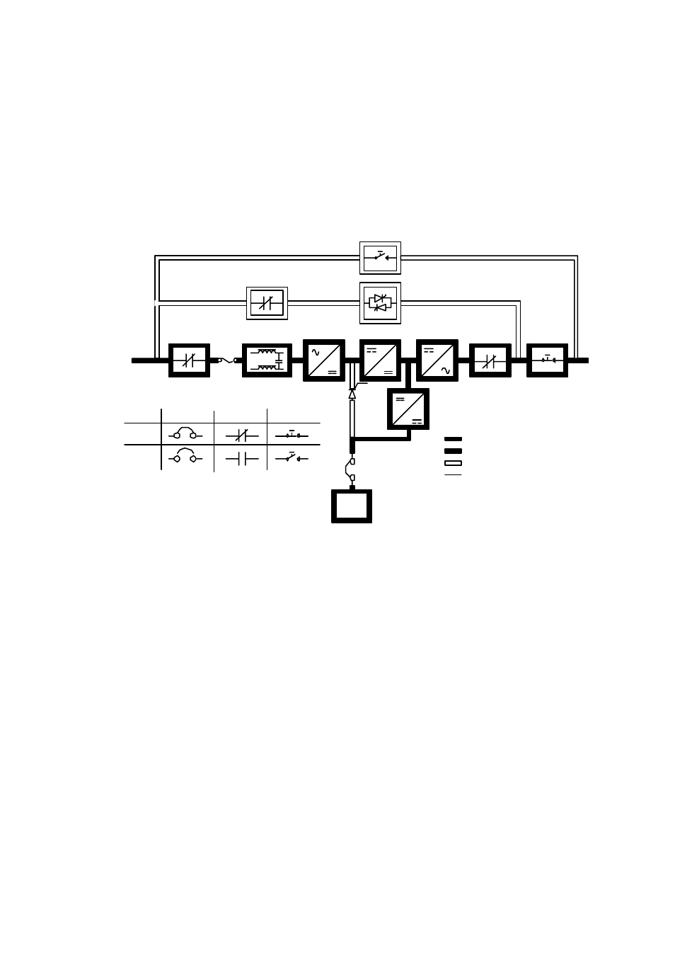
5.2.1 Normal Mode
Figure 5–2 shows the path of electrical power through the UPS system when the UPS is
operating in Normal mode.
Battery
Charger
Rectifier
Input Filter
Booster
K4
K1
Inverter
K2
Battery
Breaker
Breaker
Contactors
Closed
Open
Battery
IA2
IA1
Switches
Main Power
Trickle Current
Energized
De-Energized
Normal Mode
F1
Figure 5–2. Path of Current Through the UPS in Normal Mode
During normal UPS operation, power for the system is derived from a utility input source
through the input contactor K1 (and externally protected utility feed). “Load Protected”
appears on the LCD display and indicates the incoming power is within voltage and
frequency acceptance windows. Three phase AC input power is converted to DC using a
full-wave, six-pulse, solid-state rectifier block which supplies unregulated DC voltage to a
boost converter which in turn supplies a higher, regulated DC voltage to the inverter.
A separate internal battery charger is used to maintain the proper charge level on the
battery during normal operation. The battery charger derives its input from the booster
output and provides regulated DC voltage and charge current to the battery. The battery
charge condition is monitored by the UPS and, when abnormal, reported by the status
indicators located on the LCD display. The battery is always connected to the UPS and
ready to support the inverter should the utility input become unavailable.
Static Switch