3 battery mode, Battery mode – Powerware 9335 User Manual
Page 38
5-8
Powerware 9335 (80 kVA and 120 kVA) Installation and Operation
164201396 REV A 071103
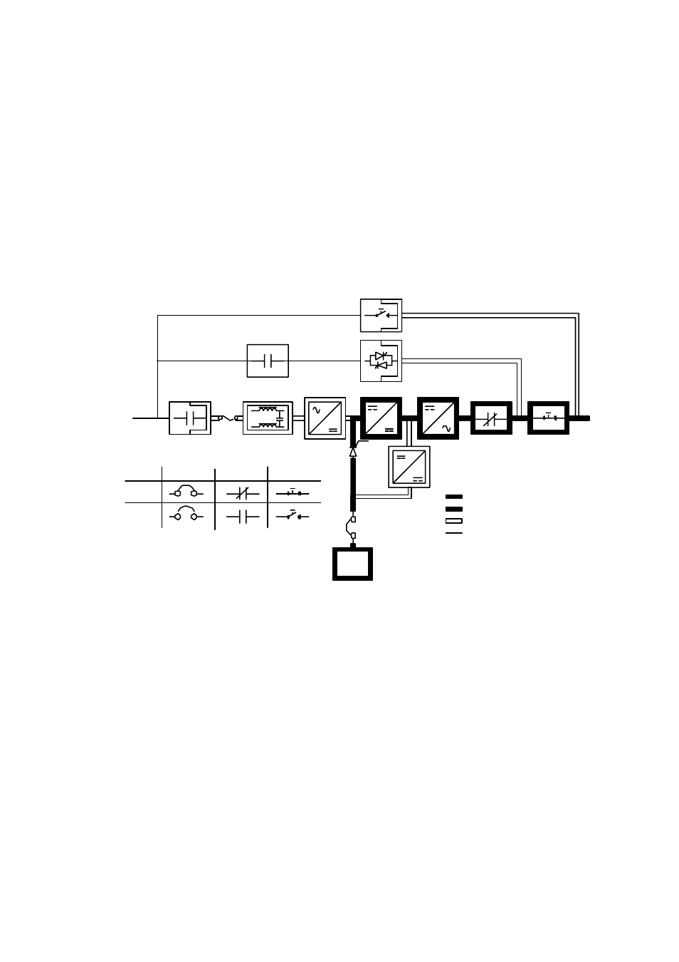
5.2.3 Battery Mode
The UPS transfers to battery mode automatically if a utility power outage occurs, or if the
utility power does not conform to specified parameters. In Battery mode, the battery
provides emergency DC power that the inverter converts to AC power.
Figure 5–4 shows the path of electrical power through the UPS system when operating in
Battery mode.
Battery
Charger
Rectifier
Input Filter
Booster
K4
K1
Inverter
K2
Battery
Breaker
Breaker
Contactors
Closed
Open
Battery
IA2
IA1
Switches
Main Power
Trickle Current
Energized
De-Energized
Battery Mode
F1
Figure 5–4. Path of Current Through the UPS in Battery Mode
During a utility power failure, the rectifier no longer has an AC utility source from which to
supply the DC output current required to support the battery charger and boost converter.
The input contactor (K1) is opened, the battery charger is turned off, and the battery SCRs
(+ and -) both receive signals to turn on to provide battery power to the system. Because
the battery SCRs are electronic devices, battery power is instantly available to the boost
converter so that the inverter and customers load can be supported without interruption. In
a single feed installation, where the bypass input is connected to the rectifier input, the back
feed protection contactor (K4) will also open. The opening of contactors K1 and K4
prevents static system voltage from bleeding backwards through the static switch and
rectifier snubber components and re-energizing the input source.
Static Switch