Introduction, Pin teleco connector, Band marked color code – Patton electronic 3224 User Manual
Page 51
Introduction
44
Model 3224 G.SHDSL IpDSLAM User Manual
C • Network Ports (RJ-21X) connector pin-out
Introduction
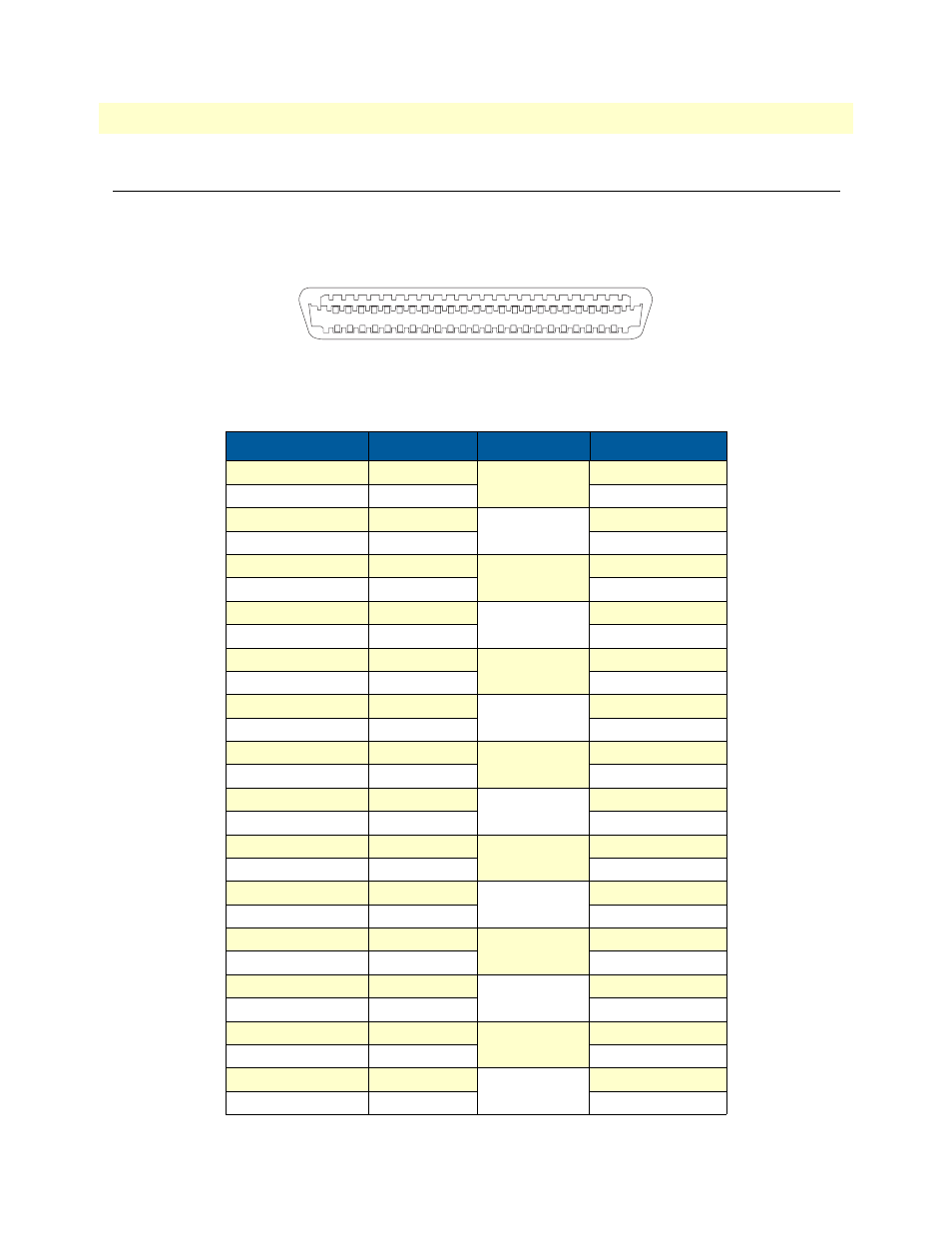
Table 4 contains the band-marked color codes for the RJ-21X, 50-pin Telco connector. The Pair Number
matches the port number on the DS0 Mapping Management page.
Figure 17. 50-pin Teleco connector
Table 4. Band Marked Color Code
Wire/Color Code Tip and Ring Pair Number 50 Pin Positions
White/Blue
Tip 1
Pair 1
26
Blue/White
Ring 1
1
White/Orange
Tip 2
Pair 2
27
Orange/White
Ring 2
2
White/Green
Tip 3
Pair 3
28
Green/White
Ring 3
3
White/Brown
Tip 4
Pair 4
29
Brown/White
Ring 4
4
White/Slate
Tip 5
Pair 5
30
Slate/White
Ring 5
5
Red/Blue
Tip 6
Pair 6
31
Blue/Red
Ring 6
6
Red/Orange
Tip 7
Pair 7
32
Orange/Red
Ring 7
7
Red/Green
Tip 8
Pair 8
33
Green/Red
Ring 8
8
Red/Brown
Tip 9
Pair 9
34
Brown/Red
Ring 9
9
Red/Slate
Tip 10
Pair 10
35
Slate/Red
Ring 10
10
Black/Blue
Tip 11
Pair 11
36
Blue/Black
Ring 11
11
Black/Orange
Tip 12
Pair 12
37
Orange/Black
Ring 12
12
Black/Green
Tip 13
Pair 13
38
Green/Black
Ring 13
13
Black/Brown
Tip 14
Pair 14
39
Brown/Black
Ring 14
14
NETWORK PORTS
1
26
25
50