Connecting the dsl ports, Cross-over rj-45-to-rj-45 ethernet cable diagram, Db-9-to-rj-45 cable diagram – Patton electronic 3224 User Manual
Page 29
Cable installation
22
Model 3224 G.SHDSL IpDSLAM User Manual
2 • Hardware installation
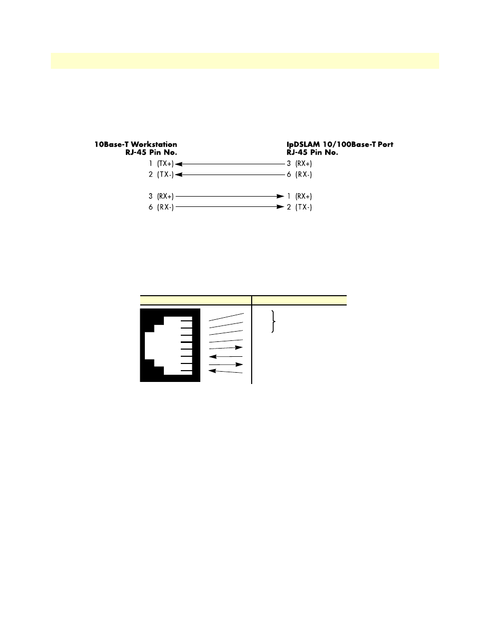
Connecting a 10/100Base-T Ethernet port to an Ethernet-capable workstation
The 10/100Base-T Ethernet ports can connect to a single Ethernet-capable workstation or PC by means of a
cross-over cable. Refer to
to assemble a cross-connect cable that will connect between the NIC Ether-
net port in the workstation and one of the IpDSLAM 10/100Base-T Ethernet ports.
Figure 11. Cross-over RJ-45-to-RJ-45 Ethernet cable diagram
Connecting the EIA-561 RS-232 configuration port (DCE configured)
Install the supplied RJ-45-to-RJ-45 cable with the DB9-RJ45 adapter between the IpDSLAM RS-232 port
(see
on page 21) and an open serial port on your computer. If you need to assemble your own cable,
refer to the pinout diagram in
Figure 12.
DB-9-to-RJ-45 cable
diagram
Connecting the DSL Ports
The remote (CPE) G.SHDSL modems are connected to the IpDSLAM via the RJ-21X cable. Consult Appen-
dix A, “Network Ports (RJ-21X) connector pin-out” in order to connect the CPE G.SHDSL modems to the
selected G.SHDSL modem port on the Model 3224.
Note
The 2-wire G.SHDSL modem lines are polarity insensitive so you
only need to match the correct twisted pairs without being concerned
about matching the individual wires of the twisted pair.
1. Connect the RJ-21X connector of the cable into the 50-pin RJ-21X receptacle on the rear of the 3224.
2. The other end of the cable has 25 non-terminated twisted-pairs for connection to punch-down blocks.
Select the twisted-pairs which will be used for active G.SHDSL modem connections and terminate on the
punch-down blocks. Only 24 of the twisted pairs will be used since there are 24 G.SHDSL modem con-
nections, each being a 2-wire connection.
6 DSR
1 CD
4 DTR
5 SG
2 RD (driven by access server)
3 TD (received by access server)
8 CTS (driven by access server)
7 RTS (received by access server)
1
2
3
4
5
6
7
8
Wired together
(No other electrical
connection)
RJ-45 Jack
Signal Name
DB-9