Model 3615 dsu hardware switch location, Model 3615 dsu switch settings – Paradyne COMSPHERE 3615 User Manual
Page 23
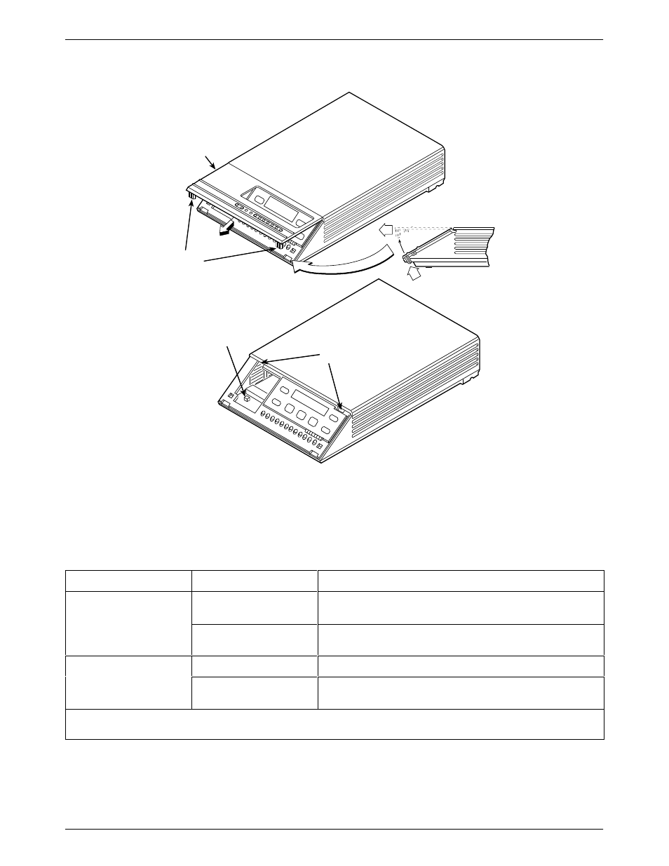
Installing the Model 3615 DualFlow DSU
2-3
3615-A2-GB20-20
December 1996
496-14499-01
SWITCH 1
HINGE TAB
LOCATIONS
FRONT BEZEL
COMSPHERE
3615
SNAP
TABS
Figure 2-1. Model 3615 DSU Hardware Switch Location
Table 2-1
Model 3615 DSU Switch Settings
Switch Position
Switch Setting
Function
S1-1
ON
(default)
Permissive V.32 DBM transmit output level of –9 dBm
S1-1
Off
Programmable V.32 DBM transmit level between –12 dBm and
0 dBm
ON
Frame ground (FG) connected to signal ground (SG)
S1-2
Off
(default)
FG connected to SG through 100 ohm resistor
ON is to the rear as you face the front of the DSU.
Off is to the front.
This manual is related to the following products: