Pin assignments, Digital network connector, Overview – Paradyne COMSPHERE 3615 User Manual
Page 104: Network connectors
D-1
3615-A2-GB20-20
December 1996
Pin Assignments
D-1
D-1
D-2
. . . . . . . . . . . . . . . . . . . . . . . . . . . . . . . . . . . . . . . . . . . . . . . . . . . . . . . . . . . . .
D-4
D-8
Overview
Pin assignments for the 3615 Series DSU connectors
and interfaces are included here. Refer to them as needed.
Refer to the COMSPHERE 3000 Series Carrier,
Installation Manual for additional pin assignments.
Network Connectors
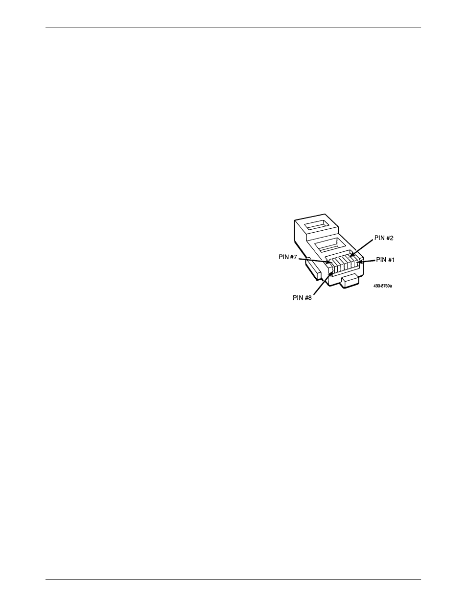
Figure D-1 shows the Model 3615 DSU’s digital
network connector, which is used for DDS and the 4-wire
Switched 56 kbps connection. Table D-1 provides its pin
assignments. Table D-2 provides the network connector
pin assignments used for the V.32 and 2-wire Switched 56
DBM, which uses a 6-pin jack (not shown in any figure).
Figure D-1. Digital Network Connector
D