Use as public address speaker, Tk-7150, Installation – Kenwood TK-7150 User Manual
Page 8
TK-7150
8
4. Use as Public Address Speaker
1. Remove the short plug from the 6-pin accessory connec-
tor on the rear of the radio. (Remove the jumpers as de-
scribed in Section 3-1.)
2. Cut off the end of the protective cover, insert the speaker
cable into the protective cover, and insert it into pins 2 and
3.
3. Install the plug and protective cover on the accessory con-
nector on the rear of the transceiver, then clamp the bot-
tom of the protective cover with the supplied tie wrap.
4. If you remove jumper shorting pins 5 and 6, the 20W PA
(public address) voice signal is output from pins 2 and 3.
(Only when the PA or SP switch is on.)
5. If you use the radio with pins 5 and 6 shorted, the internal
speaker is available.
Notes :
• Relation ship between accessory connector (6-pins) con-
nection and speaker output.
• When pins 5 and 6 are shorted; The internal speaker is
used.
• When pins 5 and 6 are open and output is from pins 2 and
3; The 20W external speaker is used.
Cut
Tie wrap
Black lead
Black/White lead
Protective cover
2
3
Short plug
Speaker cable
Fig. 4
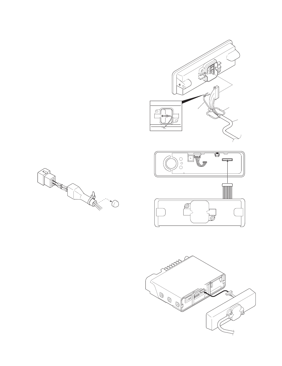
5. Single Control Head Remote Kit (KRK-9)
and Control Cable (KCT-22)
1. Lift the tab on the bottom of the transceiver, then pull the
panel away from the transceiver.
2. Remove the connector that binds the display unit to the
TX-RX unit.
3. As shown in Figure 5-1, make sure that the rubber seal is
placed above the cable, then plug the 11-pin connector
into the front panel PCB assembly.
4. Also, affix the ground wire to the front panel chassis, as
shown in Figure 5-1, with the supplied screw.
5. Choose the remote wire position (right side or left side),
then place the seal within the guide rail. Attach and se-
cure the cover using the 2 binding screws.
6. Plug the 12-pin connector (from the rear panel) to the
CN902 socket on the display PCB, as shown in Figure 5-2.
7. Push and secure the panel into the chassis so that the 6
tabs on the top and bottom are securely fixed.
8. Plug the connector from the main panel into the CN703
socket (Figure 5-3).
9. Push and secure the main panel so that the 6 tabs on the
top and bottom of the panel are securely fixed.
Rubber seal
KCT-22
Ground wire
Display unit
CN902
Rear panel
Main panel
CN703
Fig. 5-1
Fig. 5-2
Fig. 5-3
INSTALLATION