Terminal function, Display unit (x54-3400-10) (a/2), Display unit (x54-3400-10) (b/2) – Kenwood TK-7150 User Manual
Page 54: Tx-rx unit (x57-6570-10), Tk-7150
TK-7150
66
TERMINAL FUNCTION
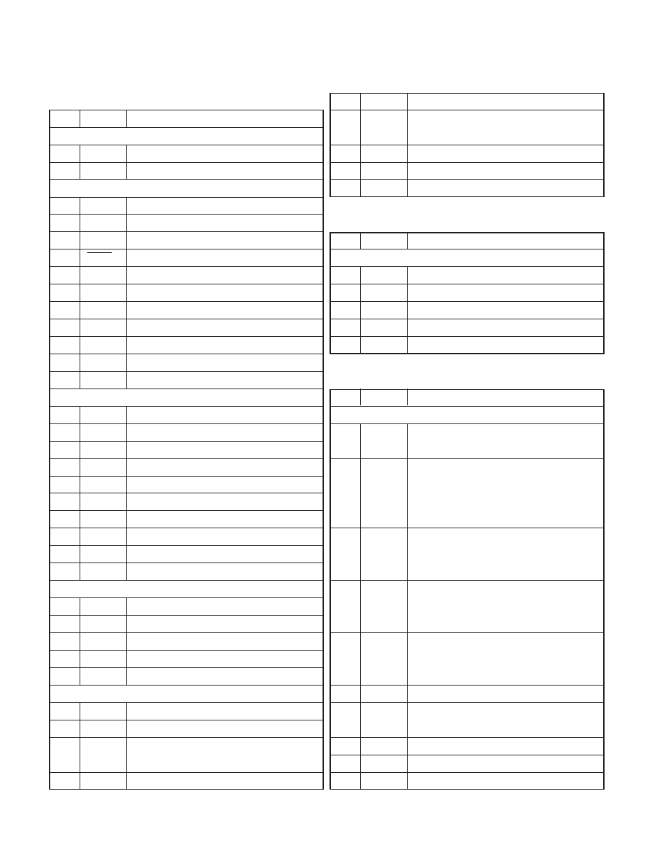
1. Display Unit (X54-3400-10) (A/2)
Pin No.
Name
Description
CN901 (To remote speaker)
1
IRS
BTL output for remote speaker output.
2
ES2
BTL output for remote speaker output.
CN902 (To TX-RX unit)
1
ME
MIC ground.
2
MIC
MIC signal output.
3
E
Ground.
4
RESET
Reset signal input.
5
TXD
Serial data input.
6
RXD
Serial data output.
7
E
Ground.
8
PSW
Power switch control signal output.
9
SB
Power input after power switch (13.6V± 15%).
10
IRS
BTL input for remote speaker output.
11
ES2
BTL input for remote speaker output.
CN905 (To LCD assy)
1
E
Ground.
2
VCC
5V.
3
CE
Enable output for LCD driver.
4
CL
Clock output for LCD driver.
5
DI
Data output for LCD driver.
6
DO
Not used.
7
DISP
Display control signal output. “L” : Display off
8
LEDA
Power output for LCD backlight.
9
LEDK
Ground for LCD backlight. “L” : Backlight on
10
NC
Non connection.
CN906 (To Display unit B/2 : CH SW)
1
E
Ground.
2
P4
SW position signal input 4.
3
P3
SW position signal input 3.
4
P2
SW position signal input 2.
5
P1
SW position signal input 1.
J901 (MIC jack)
1
DM
Serial data input for keypad MIC.
2
MIC
MIC signal input.
3
PTT
PTT signal input. “L” : TX, “OPEN” : RX
Serial data output.
4
SB
Power output after power switch (13.6V± 15%).
Pin No.
Name
Description
5
HK
Hook signal input. “L” : On hook, “H” : Off hook
Serial data input.
6
ME
MIC ground.
7
E
Ground.
8
BLC
MIC backlight control signal output. “H” : On, “L” : Off
2. Display Unit (X54-3400-10) (B/2)
Pin No.
Name
Description
W1 (To Display unit A/2)
1
P1
SW position signal output 1.
2
P2
SW position signal output 2.
3
P3
SW position signal output 3.
4
P4
SW position signal output 4.
5
E
Ground.
3. TX-RX Unit (X57-6570-10)
Pin No.
Name
Description
CN700 (To ANI board)
1
BUSY
2
EMG
Emergency signal output.
“L” : Emergency function is operated,
“H” : Emergency function is not operated
L ≤ 0.05V, H ≥ 4.6V/30kΩ load
3
KEY
TX control signal input.
Active low with 47kΩ pull-up to 5V
L ≤ 0.8V, H ≥ 2.5V
4
AUX
Emergency signal input.
Active low with 47kΩ pull-up to 5V
L ≤ 0.8V, H ≥ 2.5V
5
INH
MIC mute signal input. “L” : Mute
Active low with 47kΩ pull-up to 5V
L ≤ 0.8V, H ≥ 2.5V
6
STON
Side tone input.
7
TCNT
Speaker mute signal input. “L” : Unmute
L ≤ 0.8V, H ≥ 2.5V
8
DATA
Data signal input.
9
E
Ground.
10
8C
8V. (CN700 No.10 + CN701 No.13 = 100mA Max.)
TX sens signal output
.
Conventional “H” : Not TX, “L” : TX
LTR “H” : Not Link complete, “L” : Link complete