Operating features, Controls and functions, Tk-7150 – Kenwood TK-7150 User Manual
Page 4
TK-7150
4
OPERATING FEATURES
1. Controls and Functions
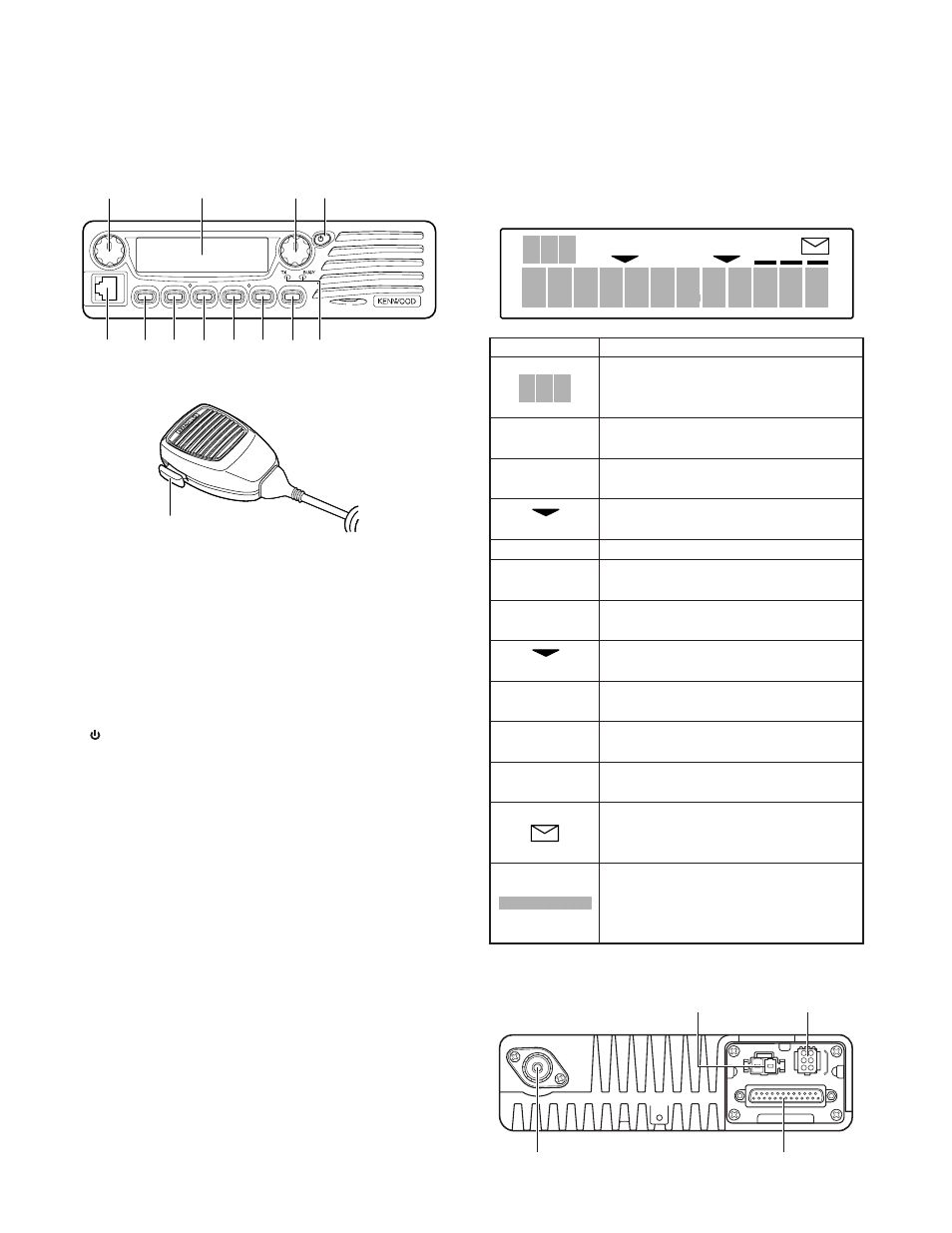
1-1. Front Panel
q
w
e
r
!0
t
y
u
o
i
!1
!2
1-2. Microphone
!3
q Volume Control
Rotate to adjust the volume level. Clockwise increases
the volume and counterclockwise decreases the volume.
w Display
(See right.)
e Selector
Rotate to select a Zone or CH/GID (channel/group ID).
Clockwise increases the Zone / CH/GID and counterclock-
wise decreases the Zone / CH/GID. The default setting is
CH/GID Up/Down.
r (Power) switch
Press to switch the transceiver ON. Press and hold for
approximately 1 second to switch the transceiver OFF.
t Microphone Jack
Insert the microphone plug into this jack.
y PF1 Key
Press this key to activate its programmable auxiliary func-
tion. The default setting is Zone Up.
u PF2 Key
Press this key to activate its programmable auxiliary func-
tion. The default setting is Zone Down.
i PF3 Key
Press this key to activate its programmable auxiliary func-
tion. The default setting is None.
o PF4 Key
Press this key to activate its programmable auxiliary func-
tion. The default setting is None.
!0 PF5 Key
Press this key to activate its programmable auxiliary func-
tion. The default setting is None.
!1 PF6 Key
Press this key to activate its programmable auxiliary func-
tion. The default setting is None.
!2 TX / BUSY LEDs
The TX LED lights red while transmitting. In Conventional
Groups, the BUSY LED lights green while receiving.
!3 PTT switch
To transmit, press and hold this switch, then speak into
the microphone. Release to receive.
1-3. Display
Indicator
Description
Displays the zone, group ID, and channel
numbers. Also displays various functions
which have been programmed by your dealer.
CALL
Appears when the squelch opens during a
2-Tone or DTMF call.
MON
Appears when the key programmed as
Monitor is pressed.
Appears when the selected Zone is added to
(left side)
the scan list.
SCN
Appears when you are using Scan mode.
SP
Appears when you are using an external
speaker.
OP
Appears when the optional scrambler board
is installed and activated.
Appears when the selected Channel/Group
(right side)
ID is added to the scan list.
A
Appears when the auxiliary A function is
activated.
B
Appears when the auxiliary B function is
activated.
OS
Appears when Operator Selectable Tone is
activated.
Appears when a FleetSync message is
stored in the transceiver memory. Appears
and blinks when a new message is received.
Displays the zone, group ID, and channel
numbers. Your dealer can program the zone,
group ID, and channel names with up to 12
characters, in place of numbers.
1-4. Rear Panel
SCN SP OP
OS
A B
MON
CALL
Power input
connector
6-pin connector
(for accessories)
25-pin connector
(for accessories)
Antenna
connector