Tk-7150, Terminal function – Kenwood TK-7150 User Manual
Page 55
TK-7150
67
TERMINAL FUNCTION
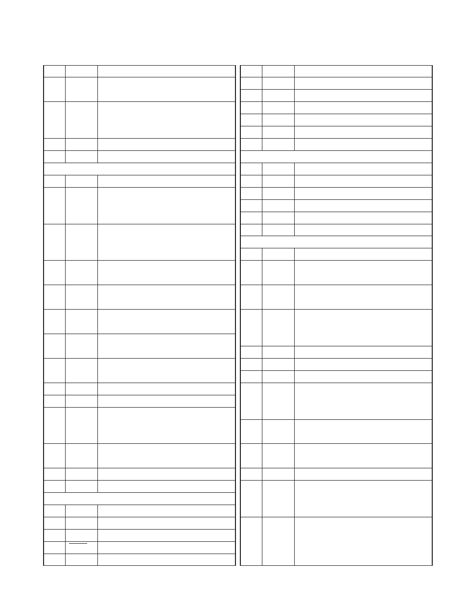
Pin No.
Name
Description
11
PTOA
PTT signal output. “L” : PTT on, “H” : PTT off
L ≤ 0.05V, H ≥ 4.6V/30kΩ load
12
DETO
Detected signal output. DC coupled. Zo ≤ 100Ω
Wide : 0.8Vp-p typ., Narrow : 0.7Vp-p typ.
(Standard modulation)
13
NC
Non connection.
14
NC
Non connection.
CN701 (To voice scrambler)
1
TXI
MIC signal input (Capacitor-coupled). Zin = 100kΩ
2
TXO
MIC signal output (Capacitor-coupled). Zo = 1kΩ
Wide : 85mVp-p typ., Narrow : 85mVp-p typ.
(Standard modulation)
3
RXI
Audio signal input (Capacitor-coupled). Zin = 27kΩ
Wide : 1.3Vp-p typ., Narrow : 1.1Vp-p typ.
(Standard modulation)
4
AC
Scrambler control signal output. “L” : On, “H” : Off
L ≤ 0.05V, H ≥ 4.6V/30kΩ load
5
BC1
Scrambler code signal output 1.
L ≤ 0.05V, H ≥ 4.6V/30kΩ load
6
BC2
Scrambler code signal output 2.
L ≤ 0.05V, H ≥ 4.6V/30kΩ load
7
BC3
Scrambler code signal output 3.
L ≤ 0.05V, H ≥ 4.6V/30kΩ load
8
BC4
Scrambler code signal output 4.
L ≤ 0.05V, H ≥ 4.6V/30kΩ load
9
NC
Non connection.
10
NC
Non connection.
11
RXO
Audio signal output. DC coupled. Zo ≤ 100Ω
Wide : 1.3Vp-p typ., Narrow : 1.1Vp-p typ.
(Standard modulation)
12
PTOS
TX signal output. “L” : TX, “H” : Not TX
L ≤ 0.05V, H ≥ 4.6V/30kΩ load
13
8C
8V. (CN700 No.10 + CN701 No.13 = 100mA Max.)
14
E
Ground.
CN703 (To Display unit A/2)
1
ME
MIC ground.
2
MIC
MIC signal input.
3
E
Ground.
4
RESET
Reset signal output.
5
TXD
Serial data output.
Pin No.
Name
Description
6
RXD
Serial data input.
7
E
Ground.
8
PSW
Power switch control signal input.
9
SB
Power output after power switch (13.6V±15%).
10
IRS
BTL output for remote speaker output.
11
ES2
BTL output for remote speaker output.
CN704 (To ACC 6-pin connector)
1
IRS
Remote speaker switch.
2
ES1
BTL output for external speaker A.
3
ES2
BTL output for external speaker A.
4
OS1
BTL output for external speaker B (PA).
5
OS2
BTL output for external speaker B (PA).
6
IGN
Ignition sense input.
J700 (ACC 25-pin)
1
NC
Non connection.
2
RXD2 *
Serial data input 2. RS-232C level. Input voltage
range = ± 30V max. L ≤ 0.4V, H ≥ 2.4V. Zi ≥ 5kΩ
3
TXD2 *
Serial data output 2. RS-232C level.
L ≤ –5V, H ≥ 5V/3kΩ load. Zo ≤ 2kΩ
4
AO3
Auxiliary output 3 (Programmable). Active low
open collector (100mA max.) (Default none).
L ≤ 0.3V
5
DI
Data signal input (Capacitor-coupled).
6
MI2
External MIC input (Capacitor-coupled).
7
E
Ground.
8
AO2
Auxiliary output 2 (Programmable). Active low
with 10kΩ pull-up to 5V (100mA max.) (Default
none). L ≤ 0.3V, H ≥ 4.8V
9
TXD3 **
Serial data output 3.
L ≤ 0.7V, H ≥ 4.2V/25kΩ load. Zo ≤ 1kΩ
10
RXD3 **
Serial data input 3.
Input voltage range = +5/0 max. L ≤ 0.8V, H ≥ 4.2V.
11
E
Ground.
12
AI4
Auxiliary input 4 (Programmable). Active low
with 47kΩ pull-up to 5V (Default none).
L ≤ 0.8V, H ≥ 2.5V
13
AI2
Auxiliary input 2 (Programmable). Active low
with 47kΩ pull-up to 5V (Default none).
L ≤ 0.8V, H ≥ 2.5V