Horn alert function, Tk-7150, Installation – Kenwood TK-7150 User Manual
Page 10
TK-7150
10
INSTALLATION
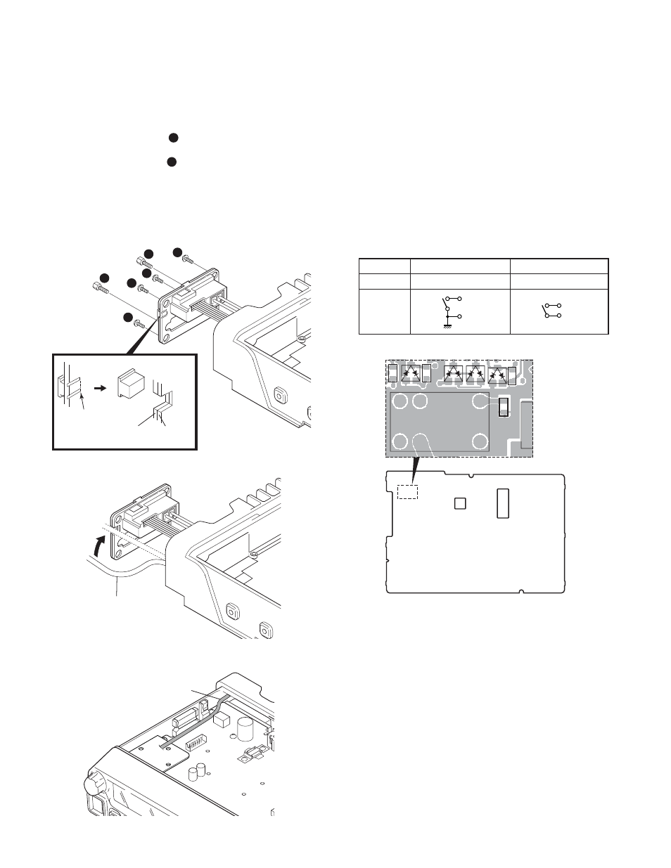
8. Horn Alert Function
The HR1 and HR2 pin of the accessory connector (25-pin)
on the rear of the transceiver is a relay and maximum current
is 1A.
8-1. Modification
1. Remove the cabinet and shielding cover from the trans-
ceiver.
2. Remove the panel.
3. Remove the short plug from the 6-pin accessory connec-
tor on the rear of the transceiver.
4. Delete R754 on the TX-RX unit.
Default
Modification
R754
Enable
Disable
State
7. Wiring of the Cable for Installing the
Built-in Type GPS Unit or Other PC Board
1. Loosen the 2 screws (
1
) to remove the D-sub 25-pin
connector.
2. Looses the 4 screws (
2
) to remove the Hardware fix-
ture.
3. Remove the CN704 connector with the 6-pin lead wire.
4. Take out the Hardware fixture.
5. Cut the packing as shown in the illustratation.
7. Tighten the 4 screws to attach the Hardware fixture.
8. Tighten the 2 screws to fix attach D-sub 25-pin connector.
Fig. 7-1
Fig. 8
Fig. 7-2
Fig. 7-3
1
2
2
2
2
1
Packing
Packing
Hareware
fixture
Cut out
Cable of GPS unit
or other board
Cable styling
HR1
HR2
HR1
HR2
R754
TX-RX UNIT
Component side