Test equipment required for alignment, Tk-7150, Adjustment – Kenwood TK-7150 User Manual
Page 37
TK-7150
37
4. Test Equipment Required for Alignment
Test Equipment
Major Specifications
1. Standard Signal Generator
Frequency Range
136 to 174MHz
(SSG)
Modulation
Frequency modulation and external modulation
Output
0.1µV to greater than 1mV
2. Power Meter
Input Impedance
50Ω
Operation Frequency
136 to 174MHz or more
Measurement Capability
Vicinity of 50W
3. Deviation Meter
Frequency Range
136 to 174MHz
4. Digital Volt Meter
Measuring Range
1 to 20V DC
(DVM)
Accuracy
High input impedance for minimum circuit loading
5. Oscilloscope
DC through 30MHz
6. High Sensitivity
Frequency Range
10Hz to 600MHz
Frequency Counter
Frequency Stability
0.2ppm or less
7. Ammeter
13A or more
8. AF Volt Meter
Frequency Range
50Hz to 10kHz
(AF VTVM)
Voltage Range
3mV to 3V
9. Audio Generator (AG)
Frequency Range
50Hz to 5kHz
Output
0 to 1V
10. Distortion Meter
Capability
3% or less at 1kHz
Input Level
50mV to 10Vrms
11. Voltmeter
Measuring Range
10 to 1.5V DC or less
Input Impedance
50kΩ/V or greater
12. 4Ω Dummy Load
Approx. 4Ω, 20W
13. Regulated Power Supply
13.6V, approx. 20A (adjustable from 9 to 20V)
Useful if ammeter requipped
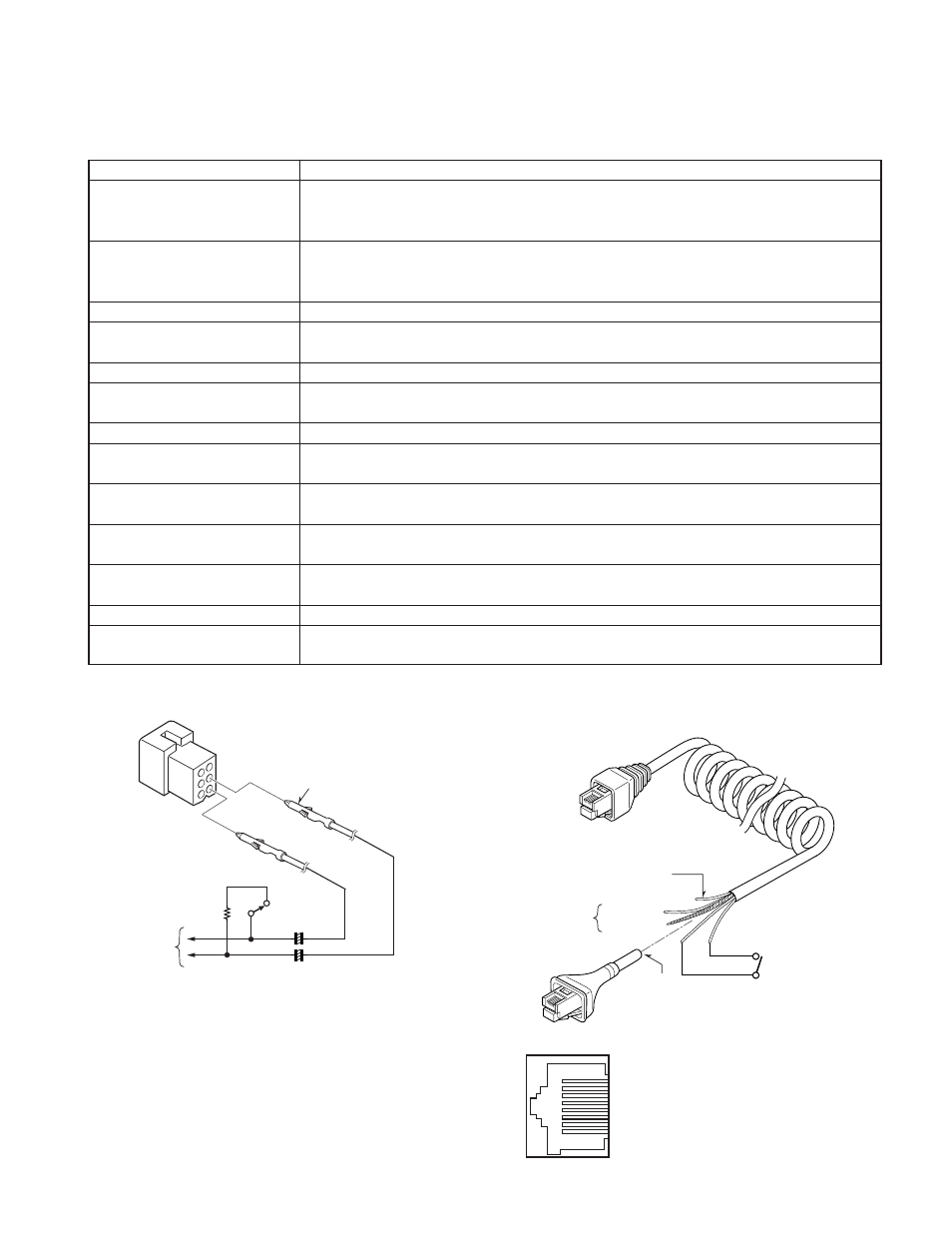
4-3. Test Cable for Microphone input
The following test cable are recommended.
4-1. Test Cable for Speaker Output
1
3
6
5
4
Crimp terminal
(E23-0613-05)
SP OUT
SP OUT
DUMMY
4Ω
/20W
SP
220µF 16WV
SP
To
AF VTVM
Distortion
meter
+
+
1
8
Cut
HOOK
(BRN)
MIC (WHT)
MICG
To
AG
AF VTVM
PTT
(YEL)
PTT
(RED)
PTT SW
Plug cord
Part No. E30-3360-08
8 pin
8 pin
1 : NC
2 : +B
3 : GND
4 : PTT/TXD1
(PC serial data
from radio)
MIC connector (Front panel view)
5 : MIC GND
6 : MIC
7 : HOOK/RXD1
(PC serial data
to radio)
8 : NC
ADJUSTMENT
4-2. Repair Jig (Chassis)
To check the voltage on the foil side of the TX-RX unit or to
adjust the PLL lock voltage, use the Repair jig (Part No. A10-
4065-02).