Rs-422a interface, Interface signals, Overview of signals (rs-422a) – Kyocera FS-1200 User Manual
Page 111: Rs-422a interface voltage levels, Serial connector
C.2. Serial (RS-232C/RS-422A) Interface (Option)
C-5
RS-422A interface
The serial interface was set to RS-232C mode before leaving the factory. However, by changing the jumper
connector on the IB-10 interface board, the interface can be changed to RS-422A mode.
In RS-232C mode, the printer can be connected to a personal computer (or similar device) equipped
with an RS-232C serial interface. (The serial interface is set to RS-232C before leaving the factory.)
In RS-422A mode, the printer can be connected to a personal computer (or similar device) equipped
with an RS-422A serial interface.
☛
The changing of the jumper connector should be carried out only by a Kyocera authorized dealer or
Kyocera certified technician. Kyocera shall not be liable for damage due to improper changing of
the jumper connector.
Interface Signals
The pins in the printer's RS-422A interface connector carry the signals listed in Table C.3.
Overview of Signals (RS-422A)
FG - Frame Ground - (Pin 1)
This pin is connected directly to the printer frame.
SG - Signal Ground - (Pin 7)
All signals can transmit between the printer and the host computer to send each signals with a signal ground.
RDB - Receive Data - (Pin 18)
RDA - Receive Data Inverted - (Pin 3)
These pins carry asynchronous data sent from the computer to the printer. (differential input)
SDB - Send Data - (Pin 10)
SDA - Send Data Inverted - (Pin 9)
These pins carry asynchronous data sent from the printer to the computer. (differential output)
RS-422A interface voltage levels
The interface signal voltage levels conform with the EIA RS-422A standard. The differential voltage varies
from 200 mV to 6V.
SERIAL Connector
The connector marked "
IOIOI" (RS-232C/RS-422A) on the rear panel is a DB-25S connector. Use a DB-25P
connector (or equivalent) for the connector on the cable.
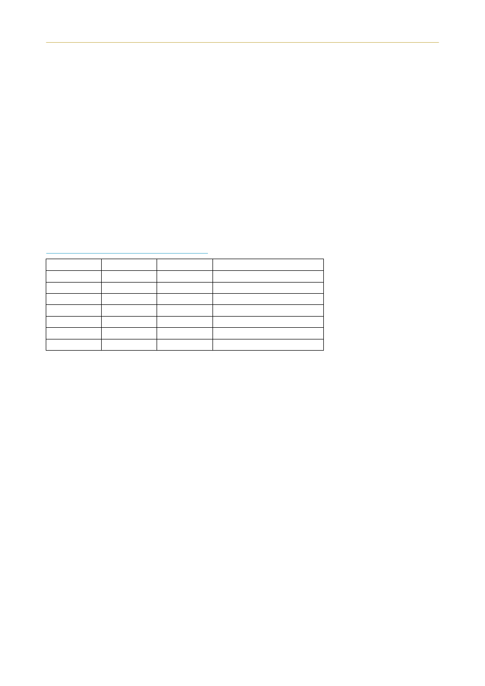
Table C.3. RS-422A Signal Pin Assignments
Pin
In/out
Signal
Description
1
–
FG
Frame ground
3
In
RDA
Receive data Inverted
7
–
SG
Signal ground
9
Out
SDA
Send data Inverted
10
Out
SDB
Send data
11
–
–
+5V DC
18
In
RDB
Receive data