Installation instructions – Sanyo CHDZ09053 User Manual
Page 50
2-40
Design of W-3WAY ECO-i SYSTEM Unit Specifi cations
1
2
3
4
5
6
7
8
4. Installation Instructions
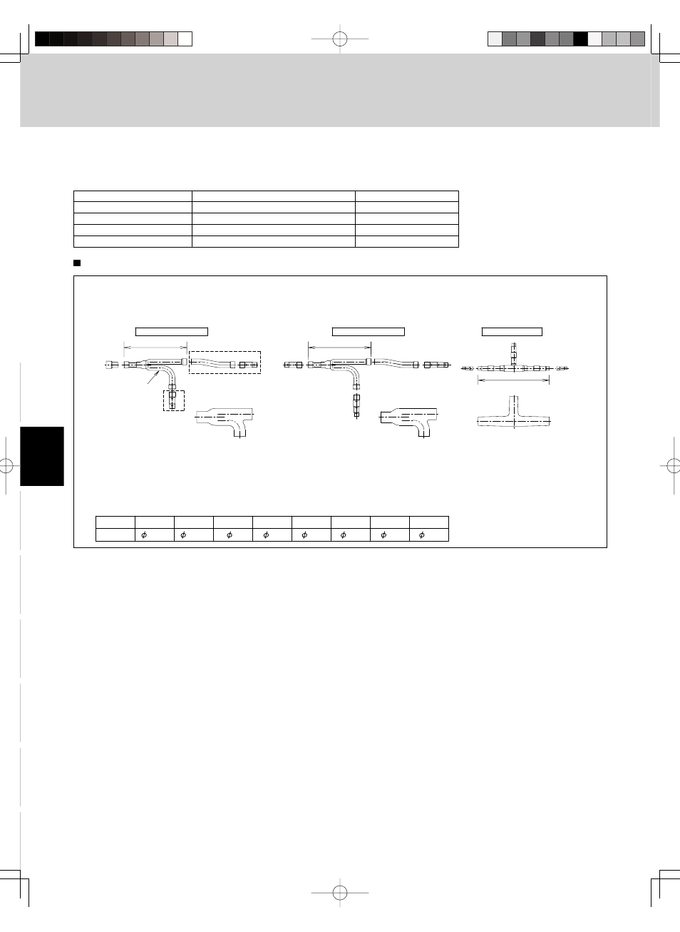
4-14. Optional Distribution Joint Kits
See the installation instructions packaged with the distribution joint kit for the installation procedure.
Table 2-11
Model name
Cooling capacity after distribution
Remarks
1. APR-CHRZP900BAB
307.100 BTU/h or less
For outdoor unit
2. APR-RZP224BAB
76.400 BTU/h or less
For indoor unit
3. APR-RZP680BAB
232.000 BTU/h or less
For indoor unit
4. APR-RZP1350BAB
460.700 BTU/h or less
For indoor unit
Tubing size (with thermal insulation)
1. APR-CHRZP900BAB
For outdoor unit (Capacity after distribution joint is 307.100 BTU/h or less.)
11-13/16
11-13/16
13-25/64
D
C
B
E
D
F
3/4
1-1/8
3/8
5/8
1/2
1
Size
7/8
1-1/4
Part B
Part C
Part D
Part E
Part F
Part G
Part H
Part I
Inch
Insulation
Insulation
Joint
Distribution
Insulation
C
C
H
I
H I
E
GF E
E FG
E
F
G
#C
C
E
D
D
E
#C
D
#C
E
F
#C
Suction Tube
Discharge Tube
Liquid Tube
Unit: in.
*Insulators for both the Suction tube and the Discharge tube are the same.
*Suction tube and Discharge tube are similar in sizes and both the tube entrances have the same diameter. So the both
Distribution joints can fit into different tubes. Since the diameter of the tube ends for both Suction and Discharge tube are
different, take care not to connect the distribution joint different. See the " # " marks on the above figures.
Note that the dimension marked with every alphabetical letter in the diagram shows the inner diameter.
Table 2-12 Dimensions for connections of each part