Model selecting and capacity calculator – Sanyo CHDZ09053 User Manual
Page 14
2-4
Design of W-3WAY ECO-i SYSTEM Unit Specifi cations
1
2
3
4
5
6
7
8
1. Model Selecting and Capacity Calculator
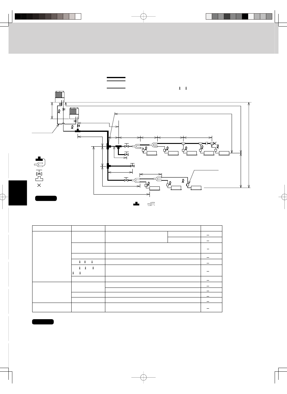
1-3. Tubing Length
H3
LM
LA
LF
LB
LC
L4
LG
LH
LD
L2
H2
L1
H1
LE
L3
C
B
4
1
2
3
5
6
7
40
1.
Main tubing length LM = LA + LB …
≤ 262 ft.
2.
Main distribution tubes LC – LH are selected according to the capacity after the
distribution joint.
3.
Sizes of indoor unit connection tubing 1 – 40 are determined by the connection tubing
sizes on the indoor units.
T-joint tubing
(header joint system)
Balance tubing
(ø9.52)
Explanation of symbols
Distribution joint
(APR: purchased separately)
Solidly welded shut
(pinch weld)
Ball valve (field supply)
T-joint (field supply)
Do not use commercially available T-joints for the liquid tubing and
parts.
R410A distribution joint
APR-CHRZP900BAB (for outdoor unit)
APR-RZP224BAB (for indoor unit)
APR-RZP680BAB (for indoor unit)
APR-RZP1350BAB (for indoor unit)
* Be sure to use special R410A distribution joints (APR: purchased separately) for outdoor
unit connections and tubing branches.
For
extension
For
extension
Max. 1.3 ft.
Max. 1.3 ft.
Solenoid valve kit
NOTE
Table 2-1 Ranges that Apply to Refrigerant Tubing Lengths and to Differences in Installation Heights
Select the installation location so that the length and size of refrigerant tubing are within the allowable range shown in the figure
below.
Item
Mark
Contents
Length (ft.)
L1
Max. tubing length
Actual length
492
Equivalent length
574
ΔL (L2 – L4)
Difference between max. length and min.
131
length from the No. 1 distribution joint
LM
Max. length of main tubing (at max. diameter)
262
1
1
2
,
2
...
...
Max. length of each distribution tube
98
L1+
+
+
Total max. tubing length including length of
984
A + B+LF+LG+LH each distribution tube (only liquid tubing)
L5
L3
Distance between outdoor units
32
H1
When outdoor unit is installed higher than indoor unit
164
When outdoor unit is installed lower than indoor unit
131
H2
Max. difference between indoor units
49
H3
Max. difference between outdoor units
13
L = Length, H = Height
Allowable tubing
length
>
>
Allowable elevation
difference
>
>
>
>
>
>
>
>
>
>
*2
6.6
Allowable length of
joint tubing
T-joint tubing (field-supply); Max. tubing length between
the first T-joint and solidly welded-shut end point
40
39
NOTE
1: If the longest tubing length (L1) exceeds 295 ft. (equivalent length), increase the sizes of the main tubes (LM) by 1 rank for
the discharge tubes, suction tubes, and liquid tubes. (Use a fi eld supply reducer.)
2: If the longest main tube length (LM) exceeds 164 ft., increase the main tube size at the portion before 164 ft. by 1 rank for
the suction tubes and discharge tubes. (Use a fi eld supply reducer.)
(For the portion that exceeds 164 ft., set based on the main tube sizes (LA) listed in the table on the following page.)