Caution – Scag Power Equipment STR User Manual
Page 30
Section 6
24
6.2 TRAVEL ADJUSTMENTS
Neutral or tracking adjustments will need to be made if:
A. The speed control lever is in neutral and the
machine creeps forward or backward. (Neutral
Adjustment)
B. The mower pulls to one side or the other when
traveling in a forward direction. (Tracking
Adjustment).
If the mower creeps forward or backward as indicated in
"A" above, the neutral linkages must be adjusted. Start
with adjusting the speed control lever and proceed as
directed. To correct the tracking of the mower (mower
pulls to one side when traveling in a forward direction),
adjust the tracking of the mower as described on page 27.
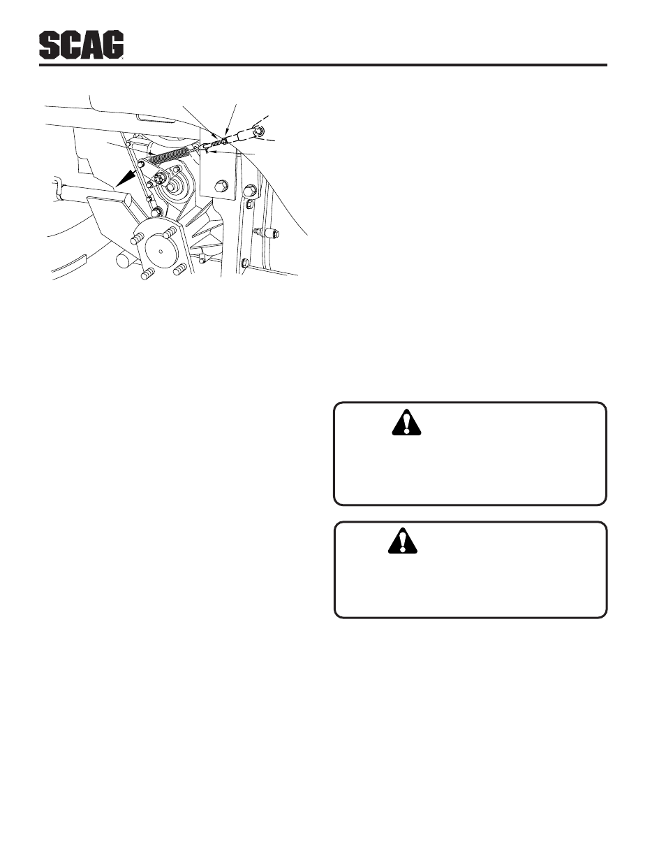
Cotter Pin
Adjusting Rod
Jam Nut
Hold Axle Lever
In This Direction
Spring
Figure 6-3 Adjusting Left Brake Linkage
B. Screw the adjusting rod into the clevis enough to
remove the slack.
C. While holding the left axle brake lever, insert the
adjusting rod into the spring and install the cotter
pin. Check for slack in the spring and linkage.
If there is slack, repeat steps B and C until the
slack is removed. If there is no slack, proceed
with step 7.
-IMPORTANT-
Be careful not to adjust the spring too tight. A tight
spring may actuate the brake linkage on the axle
and set the brake.
7. Tighten the jam nut against the clevis.
8. Install the left wheel and tire and remove the jack.
See wheel and tire removal instructions in Section 7
for the correct wheel nut torque and tightening
sequence.
Stop the engine and remove the key from the
ignition before making any adjustments. Wait
for all moving parts to come to a complete stop
before beginning work.
CAUTION:
CAUTION:
The engine and drive unit can get hot during
operation causing burn injuries. Allow engine
and drive components to cool before making
any adjustments.
Speed Control Lever Adjustment
-IMPORTANT-
Before proceeding with this adjustment, be sure that
the tire pressure in the three tires is correct, that the
caster wheels turn freely, and that the two
transmission drive belts are adjusted for the correct
tension.
1. Place the speed control lever in the neutral position
(Figure 6-4).