Scag Power Equipment STR User Manual
Page 15
9
Section 4
5. Ammeter (Figure 4-1). Indicates the condition of
the charging system. When the engine is running the
needle should be at the positive end of the meter. If
the needle is on the negative end of the meter, this
indicates a discharge condition and the machine
should be taken in for service.
6. Hourmeter (Figure 4-1). Indicates the number of
hours the engine has been operated. It operates
whenever the ignition switch key is in the ON
position. It can be used to keep track of maintenance
intervals and the amount of time required to perform
various tasks.
7. Fuse Holders (Figure 4-1). Two 20-amp fuses
protect the mower’s electrical system. To replace
fuses, pull fuse out of the socket and install a new
fuse.
8. Left Steering Control (Figure 4-1). Used to control
the mower's left wheel when traveling forward or
reverse.
9. Right Steering Control (Figure 4-1). Used to
control the mower's right wheel when traveling
forward or reverse.
10. Parking Brake Control (Figure 4-1). Used to
engage and disengage the parking brakes. Pull the
lever back and lock in place to engage the parking
brakes. Pull the lever back and move to the left to
disengage the parking brakes.
11. Fuel Tank Gauge (Figure 4-1 & 4-4). Indicates the
amount of fuel in the fuel tank.
12. Dump Valve Control (Figure 4-2). Located under
the seat, is used to “free-wheel” the mower. Pulling
the lever back and locking in place allows the unit to
move under hydraulic power. The lever must be in
this position during operation of the mower. Pushing
the lever forward and locking in place allows the
mower to be moved by hand (free-wheeling).
Figure 4-4 Seat Lock Lever
DANGER
Dump Valve Handle
Figure 4-2 Dump Valve Control
13. Hopper/Side Discharge Control (Figure 4-3). This
lever is used to select either discharge of grass into
the hopper or through the side discharge chute.
The release lever is used to aid the control lever when
switching the gate between side discharge and hopper
discharge.
Discharge
Control
Lever
Release Lever
Figure 4-3 Hopper/Side Discharge Control
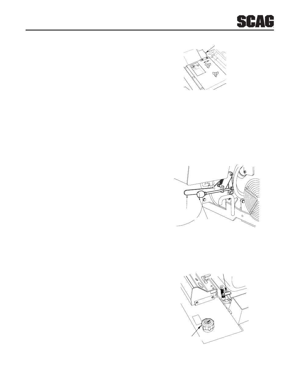
14. Seat Lock Lever (Figure 4-4). Used to lock the seat
in the down position.
Seat Latch
Fuel Cap/Gauge