Drive unit installation, 10 drive unit installation, Installation – Simrad AUTOPILOT SYSTEM AP50 User Manual
Page 91
Installation
20221032B
89
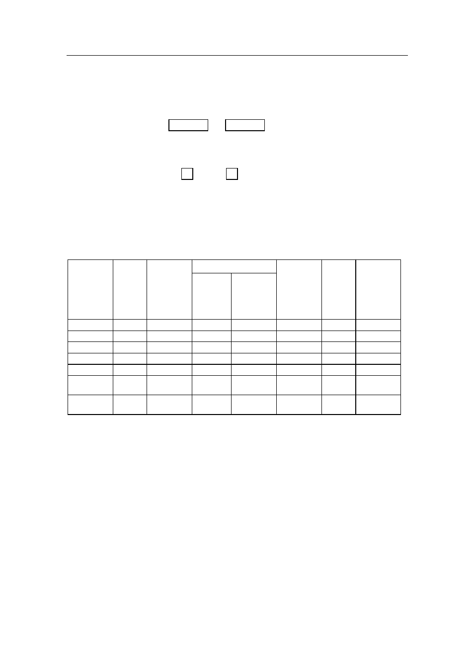
4.10 Drive Unit Installation
The relation between drive units, drive unit voltage, input
voltage, drive output, and interfacing to steering gear are shown
in Table 4-2 and Table 4-3. The AP50 system detects whether a
reversible motor or a solenoid is connected and outputs the
correct drive signal automatically.
Refer to the connecting diagrams for the different drive units on
pages 91 through 93.
Installation instructions for the drive units are found in the
manuals for the individual units.
The maximum drive current capabilities of the J50 and J50-40
Junction Units are different. Use the table below as a reference
and observe the notes.
HYDRAULIC PUMPS
RAM
CAPACITY
MODEL MOTOR
VOLTS
JUNCTION
UNIT
MIN.
cm
3
(cu. in.)
MAX.
cm
3
(cu. in.)
FLOW
RATE AT 10
bar
cm
3
/min.
(cu. in./min.)
MAX.
PRES-
SURE
bar
PWR.
CONSUMP-
TION
RPU80
12
J50
80 (4.9)
250 (15.2)
800 (49)
50
2,5-6 A
RPU160
12
J50
160 (9.8)
550 (33.5)
1600 (98)
60
3-10 A
RPU200
24
J50
190 (11.6)
670 (40.8)
2000 (122)
80
3-10 A
RPU300
12
J50-40
290 (17.7)
960 (58.5)
3000 (183)
60
5-25 A
RPU300
24
J50
290 (17.7)
960 (58.5)
3000 (183)
60
2,5-12 A
RPU3
24
J50
370 (22.4)
1700 (103)
3800/5000
(232/305)
40 7-22
A
RPU1
12
J50
140 (8.5)
600 (36.6)
1400/2000
(120/185)
40 7-22
A
Steering Gear Interface: Hydraulic Plumbing
Table 4-2 Hydraulic Pumps