Rudder feedback calibration – Simrad AUTOPILOT SYSTEM AP50 User Manual
Page 124
Simrad AP50 Autopilot
122
20221032B
Refer to the drive unit tables on pages 89 and 90 for
information. The clutch/bypass voltage is automatically set to
coincide with the drive unit voltage. During the rudder test, the
AP50 system will also automatically detect whether the drive
unit is a reversible motor or whether it is solenoid operated.
To change the voltage selection, rotate the course knob.
Note !
The Drive unit voltage setting does not apply when operating
solenoids on a continuous running pump/steering gear. Hence,
the output voltage to the solenoids will be the same as the input
voltage.
Proceed to the next menu item by pressing the
(STBD)
button.
Rudder Feedback Calibration
(Not applicable for analog drives).
DOCKSIDE
Master operation Yes
Boat type Displacement
Boat length
0-50 FEET
Drive unit voltage 12V
Rudd feedb cal STBD ---
Rudd feedb cal PORT ---
No
Yes
For systems using an RF45X Rudder Feedback Unit, be sure that
the unit has been mechanically aligned (see page 79) before
attempting Rudder feedback calibration.
This function enables you to compensate for non-linearity in the
mechanical transmission between the rudder and the rudder
feedback unit.
DOCKSIDE
Turn Rudder max. STBD
00
P S
00
Adjust?
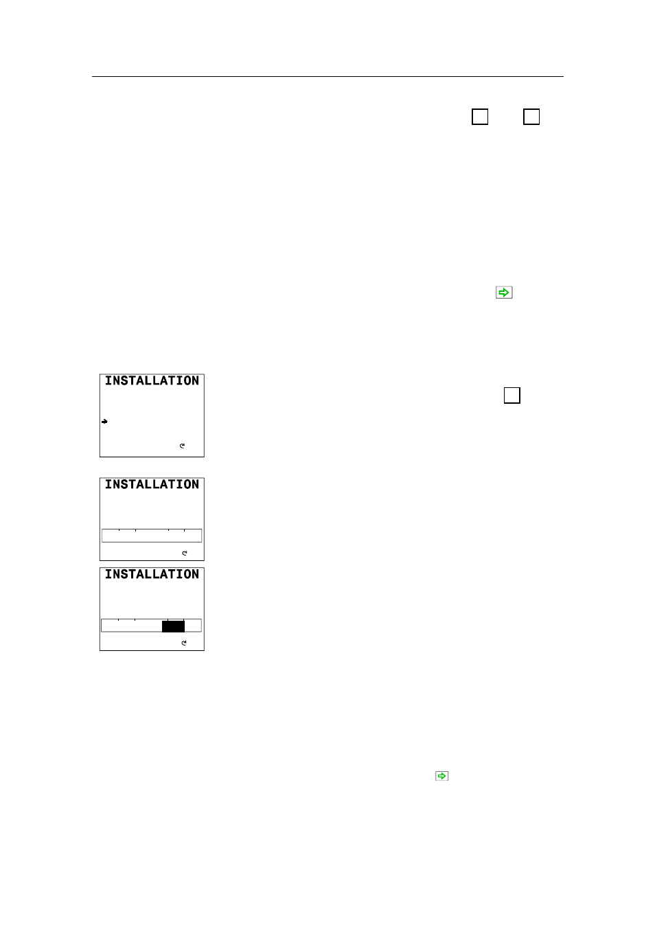
Select Rudder feedback calibration STBD by turning the
course knob clockwise. “Turn Rudder max STBD” will be
displayed on the screen.
Manually turn the helm wheel to starboard until the rudder stops
at maximum starboard rudder.
DOCKSIDE
Turn Rudder max STBD
25
P S
25
Adjust?
The value shown on the display is the value read by the feedback
unit before any adjustment is made. The bargraph indicates to
which side the rudder is positioned. Be sure to set the correct
rudder angle and direction by turning the course knob. The
autopilot uses this value as physical stop. Physical stop minus 2°
will be used as “max. rudder limit” and determines how far the
autopilot can under any circumstance, drive the rudder.
Note !
If the rudder feedback unit is mounted upside down, the
displayed rudder angle may be to the opposite side before you
start the adjustment (arrow pointing to Port). In this case, turn
the course knob starboard until the rudder angle indicator
displays the correct starboard value.
Advance to the next step by pressing the (STBD) button.
Manually turn the helm wheel to port until the rudder stops at
maximum port rudder.