Simrad AUTOPILOT SYSTEM AP50 User Manual
Page 102
Simrad AP50 Autopilot
100
20221032B
If the compass is deck-mounted or bulkhead-mounted
athwartship with the cable gland pointing aft, little if any offset
correction is required. When the cable gland points forward, a
180° correction is required.
When mounting the compass on a bulkhead alongship, a +90° or
-90° correction is needed, dependent on whether it is a port or
starboard bulkhead.
Select a location that provides a solid mounting place free from
vibration as close to the vessel's center of roll and pitch as
possible (i.e. close to the water line). It should be as far as
possible from disturbing magnetic influences, such as the
engines (minimum of 2 m), the engine ignition cables, the air-
conditioning, any refrigerators, other large metal objects, and
particularly the drive unit.
Use the supplied mounting kit and drill the holes through the
center of the slots in the sensor or the mounting brackets.
Note !
The compass faceplate on the rate compass is the TOP. NEVER
mount it upside down! Level the sensor as close to horizontal as
possible.
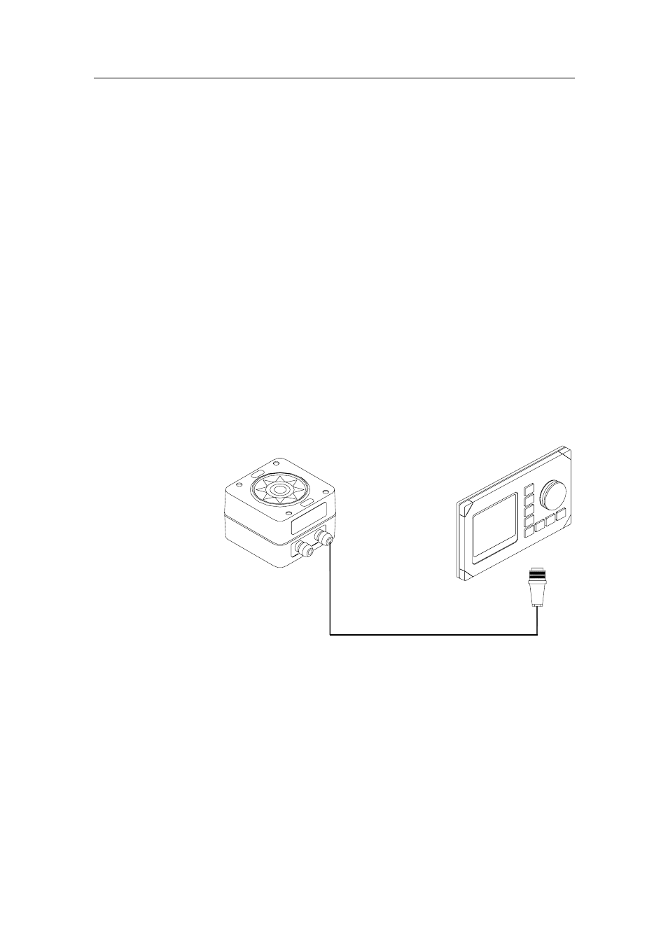
AP50
CONTROL
UNIT
RATE
COMPASS
Figure 4-26 RC25/RFC35R Connection to AP50 Control
Unit
• Connect the RobNet connector to the AP50 Control Unit (or
CI300X or NI300X if installed).
• Alternatively, if there is no free receptacle, cut the connector
from the cable and connect the wires in parallel with the
wires going from the junction unit to the control unit. Do not
connect the yellow and the green wires and ensure that they
do not connect with the terminal or chassis.